
Many machines repeat the same pattern of outputs in a fixed order, cycle after cycle. A sequencer stores each step as one word in a table and steps through it, so a whole cycle needs only a few rungs of ladder logic.
Traffic lights, wash cycles and indexing tables all follow a fixed list of output patterns. A PLC sequencer instruction drives that list from a data table, which keeps the ladder short and the step data easy to change.

What Is a PLC Sequencer Instruction?
A PLC sequencer instruction is a table driven instruction that copies one word from an array of step patterns to an output word each time it is triggered, then moves its position pointer to the next step. It replaces long chains of contacts and coils, much as a drum switch once did in relay panels, and works best alongside the basics in ladder logic for beginners.
Control.com describes sequencing as running the same steps in a fixed order for every new batch, which is why it is common in batch work. The same article notes that a sequencer takes far less memory than building the same result from separate timers and counters.
Each word in the array holds one step, and each bit in that word maps to one output, such as a lamp, valve or motor starter. Reading those patterns comfortably needs the binary basics in number systems.
SQO, SQI and SQL Explained
Moves the masked word at the current position to a destination, usually an output word.
Compares masked input data with the word at the current position and sets a match bit.
Copies a source word into the array at the current position.
In the Logix 5000 PLC sequencer instruction set, SQI is the input compare, while the older SLC 500 family calls it SQC, the sequencer compare. Rockwell asks you to use the same control tag for an SQO, SQI and SQL that work on the same array, so all three share one position pointer.
You can find the instructions in the application specific chapter of the SLC 500 manual and in the Logix instruction help. The controller families are compared in types of Allen Bradley PLCs.
Electromechanical drum sequencers used a rotating drum with pegs that pushed contacts open and closed. A PLC sequencer instruction does the same job, with each array word playing the part of one peg row on that drum.
The Six Operands of SQO
Every PLC sequencer instruction in the Rockwell family uses the same set of operands, so learning SQO once makes SQI and SQL easy to read.
| Operand | What It Holds | Practical Note |
|---|---|---|
| Array or File | First element of the step table | Step 0 is a spare, real steps start at 1 |
| Mask | Bits that are passed (1) or blocked (0) | Use a tag to change it at run time |
| Destination | Word that receives the step data | Often an output word or a buffer tag |
| Control | CONTROL tag with EN, DN, ER, LEN and POS | Share it with matching SQI and SQL |
| Length | Number of steps in the sequence | Set to the last step number used |
| Position | Current step pointer | Starts at 0, wraps back to 1 |
In the SLC 500, the control element lives in an R6 file and is three words long. Word 1 holds the length and word 2 holds the position, which is the same pointer idea used in bit shift and rotate instructions.
Rockwell explains that the position increments each time the rung goes from false to true. When the position becomes greater than or equal to the length, it returns to 1, not 0, and the DN bit is set when the position equals the length.
Leave array element 0 empty or fill it with a safe all off pattern. Because the pointer wraps to 1, element 0 is used only after a reset, which makes it a natural home state.
How the Mask Works
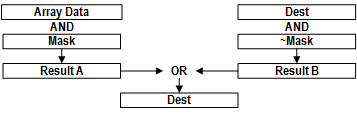
The mask lets one PLC sequencer instruction control only some bits of a word, while other logic keeps control of the rest. Rockwell states that the mask is ANDed with the array word, the inverse of the mask is ANDed with the existing destination, and the two results are ORed together.
Example, 8 bit view:
Step word = 12 = 0000 1100
Mask = 63 = 0011 1111
Old destination = 192 = 1100 0000
Step AND Mask = 0000 1100 = 12
Destination AND NOT Mask = 1100 0000 = 192
New destination = 12 OR 192 = 204 = 1100 1100
In this example, bits 6 and 7 belong to other logic and stay on, while bits 0 to 5 follow the step table. This is the same AND and OR logic you use with compare instructions and masked moves.
Sequencer Mask Calculator
6 Powerful Steps to Build a Sequencer Program
The trigger is usually a timer done bit, so each step lasts a fixed time, as covered in TON, TOF and RTO timers. You can also advance on a sensor, a counter or a push button so the sequence follows the real process.
Because the PLC sequencer instruction acts on a false to true transition, the trigger rung must go false again before the next step. A self resetting timer or a one shot from ONS, OSR and OSF handles this neatly.
Worked Example: Two Way Traffic Light
Take a crossing with two roads. Bits 0, 1 and 2 drive red, yellow and green for road A, and bits 3, 4 and 5 drive red, yellow and green for road B, so the mask is 63.
| Step | Road A | Road B | Binary | Decimal | Time |
|---|---|---|---|---|---|
| 1 | Green | Red | 0000 1100 | 12 | 30 s |
| 2 | Yellow | Red | 0000 1010 | 10 | 4 s |
| 3 | Red | Red | 0000 1001 | 9 | 2 s |
| 4 | Red | Green | 0010 0001 | 33 | 30 s |
| 5 | Red | Yellow | 0001 0001 | 17 | 4 s |
| 6 | Red | Red | 0000 1001 | 9 | 2 s |
For this PLC sequencer instruction, set the length to 6 and the position to 0, and load the step times into a second array indexed by the same position. A timer preset fed from that array gives each step its own duration, a trick that relies on data move instructions.
The two all red steps in the table are a real traffic engineering practice called the clearance interval. They let vehicles already inside the junction leave before the other road gets a green light.
Second Example: Washing Machine Cycle
A small industrial washer has a fill valve on bit 0, a drum motor on bit 1, a heater on bit 2, a drain valve on bit 3 and a spin command on bit 4. The steps fill (1), heat and wash (6), drain (8), rinse fill (1), rinse (2), drain (8) and spin (24).
Here the step should not advance only on time. Use an SQI to compare level and temperature switches with an input pattern table, and advance only when the match bit is true, a pattern that also suits ISA 88 batch control phases.
Always build a hold step into a wash or batch sequencer. When a door switch opens or a level is lost, move to a safe pattern and keep the position so the cycle can resume from the same step.
PLC Sequencer Instruction vs SFC and Step Counters
- Very short ladder for long fixed cycles.
- Step patterns change by editing data, not code.
- Low memory use, as Control.com notes.
- Easy to add SQI feedback for each step.
- Branching and parallel paths are awkward.
- Maintenance staff find bit patterns hard to read.
- Mask mistakes can switch the wrong outputs.
- Online troubleshooting needs a bit table.
For sequences with branches, parallel paths and many conditions, a sequential function chart is clearer. Many engineers also use a simple step number with compare instructions or a CASE statement in structured text programming.
Commissioning Checklist for Sequencers
- Confirm the length matches the last used step.
- Check that element 0 holds a safe all off pattern.
- Verify the mask covers only the bits this sequencer owns.
- Make the trigger rung go false between steps.
- Add a first scan reset of the control tag.
- Test the hold and resume behaviour with the real interlocks.
- Print the step table and tape it inside the panel door.
During testing, force the inputs, watch the position value step by step and compare each output with the printed table. Hardwired safety interlocks must stay outside the sequencer logic, just like the trip logic in first out alarm logic.
Troubleshooting Common Sequencer Faults
If the PLC sequencer instruction jumps two steps at once, the trigger is probably staying true or a second rung also drives the control tag. If outputs never change, check that the destination is not overwritten later in the scan by another move or an OTE.
An ER bit usually means the length or position points outside the array. A wrong order of rungs inside a routine called by JSR and JMP can also make the PLC sequencer instruction appear to skip, so check the scan order.
SLC 500 Instruction Set Reference Manual
SQI and SQO Ladder Tutorial Video
PLC Sequencer Instruction FAQ
It copies one step pattern from a data array to an output word each time its rung goes true. It then advances a position pointer to the next step in the table.
This lets one instruction run a whole repeating cycle of outputs. Changing the cycle only means editing the array values, not rewriting the ladder rungs.
SQO sends a masked step word to a destination, usually a group of outputs. SQI compares masked input data with the word at the current position.
The SQI match bit tells the program that the current step has really finished in the field. Using both together with one control tag gives a sequence with real feedback.
Rockwell designed the instruction so the pointer wraps to 1 once it reaches the length. Element 0 is used only after a reset of the control tag.
Engineers therefore keep element 0 as a safe home pattern with every output off. A first scan reset then puts the machine into that home state at power up.
Write a 1 for every bit the sequencer should control and a 0 for every other bit. Convert that binary pattern to decimal or hex and enter it as the mask.
For six outputs on bits 0 to 5 the mask is binary 111111, which is 63. Bits 6 and above then remain under the control of other logic.
The position advances only when the rung goes from false to true. A timer done bit, a sensor, a counter or a push button can supply that transition.
The rung must go false again before the next step can happen. A self resetting timer or a one shot makes sure the sequence moves one step at a time.
Choose SFC when the sequence has branches, parallel paths or many step conditions to check. Its graphical layout is much easier for maintenance staff to follow when the machine is running online.
A sequencer suits a fixed, repeating list of output patterns with simple timing. Many plants mix both methods and pick the one that fits each machine.
Rockwell lists SQO for CompactLogix, ControlLogix and GuardLogix families in its Logix instruction help. The SLC 500 and MicroLogix families provide SQO, SQC and SQL in ladder logic.
Other brands offer drum or sequencer function blocks with similar behaviour. Always check the maximum length limit and the bit width in the manual for your own controller model.
Related Articles
- Sequential Function Chart SFC in PLC
- PLC Bit Shift and Rotate Instructions
- PLC Shift Register SHL and SHR
- PLC Timer Instructions TON, TOF and RTO
- PLC Data Move Instructions
External References
- SLC 500 Instruction Set Reference Manual, Rockwell Automation
- Sequencer Output SQO, Rockwell Automation
- Programmable Logic Controller, Wikipedia
What We Learn Today
- A PLC sequencer instruction copies one step word from an array to an output word on each false to true rung transition, then advances its position.
- SQO drives outputs, SQI or SQC checks inputs and SQL loads data, and all three share one control tag holding length and position.
- The mask passes only chosen bits, so Destination equals Step AND Mask OR Destination AND NOT Mask, which protects bits used by other logic.
