
A small puck inside the sensor head can turn a weak RTD or thermocouple signal into a robust 4 to 20 mA loop right at the thermowell. Choosing, wiring and configuring it well decides whether your temperature reading stays steady for years.
Mounting the transmitter inside the connection head removes long sensor cables and compensating wire from the field. This guide explains wiring, isolation, configuration, vibration limits and a quick mA calculator for daily commissioning work.

What Is a Head Mount Temperature Transmitter?
A head mount temperature transmitter is a compact, loop powered electronic module that sits inside the connection head of a temperature sensor and converts the RTD or thermocouple signal into a standard 4 to 20 mA output, often with HART. It is the most common form of temperature transmitter on Indian process plants.
Because the conversion happens a few centimetres from the sensing element, the weak millivolt or ohm signal never travels through long field cables. Only a robust current signal leaves the head, as explained in 4 to 20 mA current loop basics.
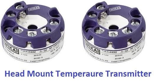
The module is usually a round puck that fits the standard DIN Form B head, held by two spring loaded screws. Sensor wires land on one side, and the two loop wires land on the other, so the whole assembly behaves as a two wire transmitter.
Electrical Volt notes that a head mounted unit removes the need for RTD lead wire compensation and thermocouple compensating cable, because the sensor wires end inside the head. Only ordinary instrument cable runs back to the control room.
How the Transmitter Converts a Sensor Signal
For a thermocouple, the microprocessor adds cold junction compensation from a sensor beside the terminals, linearises the reading and scales it to the configured range. Cold junction handling is covered further in cold junction compensation in thermocouple circuits.
Head Mount vs DIN Rail and Field Mount Styles
Puck inside the sensor connection head, loop wired from the field.
Module clipped on a 35 mm rail inside a panel or junction box.
Own dual compartment housing near the sensor, often with display.
Control Engineering described the AutomationDirect ProSense range as a clear example. Its head mounted models fit any DIN Form B head and accept 8 to 35 V dc, while its DIN rail models accept 12 to 35 V dc, and both are reverse polarity protected.
Measure the real ambient temperature at the head on a running line before you order. If it is close to the transmitter datasheet limit, move the electronics to a field mount or DIN rail unit.
Connection Head Types and Mounting
The common connection head form for these modules is DIN Form B, defined in the old DIN 43729 and now in EN 50446. Heads come in die cast aluminium, stainless steel or plastic, with screw or hinged covers, and the cable enters through a cable gland.
A tall cover suits a display unit. The head screws onto the neck tube that connects to the thermowell, so check thread sizes and the insert length before ordering.
Wiring RTD and Thermocouple Inputs
A 3 wire Pt100 is the usual choice in Indian plants, because the third wire lets the transmitter cancel lead resistance. The terminal numbering differs by maker, so follow the label on the module and the guide on RTD sensor connections.
For a thermocouple, the plus and minus legs land directly on the input terminals, and polarity must be correct. Inside the head the legs are short, so no thermocouple extension wire is needed, which removes a common source of error.
The loop pair is a shielded twisted pair, with the shield earthed at one end only, usually in the control room. This simple rule avoids most ground loop problems on long cable runs.
Emerson states that the Rosemount 644 updates each sensor reading in 0.5 second or less. That speed is fast enough for almost every temperature loop, since the sensor and thermowell respond far more slowly.
Isolation, Accuracy and Ambient Effects
Galvanic isolation between sensor and loop stops earth currents from a grounded thermocouple tip flowing into the output circuit. Emerson tests the Rosemount 644 input to output isolation at 620 V rms, and the idea is explained in galvanic isolation.
The datasheet adds a digital to analog error of 0.03 percent of span for the mA output, on top of the digital accuracy shown above. Remember that the sensor tolerance class often dominates the total error, as shown in Pt100 vs Pt1000 comparisons.
Head Mount Temperature Transmitter Output Formula
A head mount temperature transmitter maps its configured range linearly onto 4 to 20 mA, with 4 mA at LRV and 20 mA at URV.
Percent of span = (T minus LRV) ÷ (URV minus LRV) × 100
Example:
LRV = 0 °C, URV = 200 °C, T = 85 °C
Span = 200 minus 0 = 200 °C
(85 minus 0) ÷ 200 = 0.425
I = 4 + 16 × 0.425 = 4 + 6.8
I = 10.80 mA, 42.50 percent of span
Transmitter mA Output Calculator
Second Worked Example: Reading Back a Temperature
Suppose a loop configured for 0 to 200 °C shows 15.2 mA at the marshalling cabinet. Rearranging the formula gives T = LRV + (I minus 4) ÷ 16 × span.
So T = 0 + (15.2 minus 4) ÷ 16 × 200 = 11.2 ÷ 16 × 200 = 140 °C. If the local indicator shows 160 °C, the DCS range and the transmitter range probably do not match.
7 Smart Steps to Install a Head Mount Temperature Transmitter
Step six is where most faults start, because a 3 wire RTD configured as 2 wire or a type J configured as type K gives a believable but wrong value. The full procedure is in temperature transmitter configuration and ranging.
For step seven, follow the site instrument loop checking procedure and record as found values first.
Configuration With HART and PC Tools
A smart head mount temperature transmitter is configured with a HART communicator, a PC tool with a USB modem, or in newer models a Bluetooth or NFC app. The way the digital signal shares the wires is covered in HART protocol basics.
Typical settings are sensor type, number of wires, units, range, damping, alarm direction and tag. Sensor fault behaviour, upscale or downscale, should follow plant philosophy, as described in burnout function in temperature transmitter notes.
Emerson lists NAMUR alarm levels of 21 mA high and 3.6 mA low, with saturation at 20.5 mA and 3.8 mA. These values follow the NAMUR NE43 standard, which lets the DCS tell a failed sensor from a real process value.
Before leaving the site, read back the full configuration and save it as a file against the tag number. A replacement unit can then be loaded in minutes during a breakdown.
Sensor Matching and Dual Sensor Features
A calibrated Pt100 has its own Callendar Van Dusen constants on its certificate. Entering them into the head mount temperature transmitter, called sensor matching, removes most of the interchangeability error.
Emerson describes a Hot Backup option on the Rosemount 644 where, if the primary sensor fails, a second sensor takes over and prevents a measurement failure, along with a sensor drift alert.
Vibration, Heat and Hazardous Area Limits
The Rosemount 644 HART version is rated for 10 to 60 Hz at 0.35 mm displacement and 60 to 1000 Hz at 5 g peak acceleration. Compressor discharge lines and pump casings can exceed such levels, so check vibration before choosing a head mounted unit.
In hazardous areas, the transmitter and head together must carry a valid Ex certificate, either flameproof Ex d or intrinsically safe Ex i. The difference is explained in explosion proof vs intrinsically safe instruments, and an intrinsically safe loop also needs a barrier or isolator.
- Very short sensor wiring, so low noise pickup.
- No compensating cable or lead wire errors.
- Fewer panel modules and less cabinet space.
- HART diagnostics right at the measurement point.
- Electronics face process heat and vibration.
- Usually no local display in small heads.
- Access needs a ladder or platform at high points.
- Replacement needs the head cover opened in the field.
Selecting the Right Model
- Sensor types needed: Pt100, Pt1000, J, K, N, mV or ohm.
- Single or dual sensor input and Hot Backup need.
- Output: 4 to 20 mA, HART, PROFIBUS PA or FOUNDATION Fieldbus.
- Ambient temperature and vibration at the head.
- Ex certification and SIL capability for the loop.
- Head form, cover height and gland entry size.
Troubleshooting a Head Mounted Transmitter
A reading stuck at the upscale or downscale alarm usually means an open sensor or a loose terminal inside the head. Measure the sensor with a multimeter after disconnecting it, and compare it with the Pt100 or thermocouple table.
An unstable reading often comes from moisture inside the head, a damaged gland or a shield earthed at both ends. A low or noisy current can also be a loop supply problem, so check it with the HART loop voltage budget calculator and the HART resistor value.
Rosemount 644 Temperature Transmitter Datasheet
Temperature Transmitter Connection Video
Head Mount Temperature Transmitter FAQ
It is a small loop powered module fitted inside the connection head of an RTD or thermocouple assembly. It converts the sensor signal into a 4 to 20 mA output, often with a HART signal on top.
Because the conversion happens at the sensor, weak signals do not travel through long cables. This reduces noise pickup and removes compensating cable from the field wiring.
A DIN rail unit clips onto a rail inside a panel, so sensor wires must run all the way to that panel. A head mounted unit sits at the sensor and sends only the current signal back.
The electronics are often very similar in both styles. The choice mainly depends on ambient conditions, vibration, cabinet space and how many points sit close together.
Most universal models accept Pt100 and Pt1000 RTDs, common thermocouple types such as J, K, N, R, S and T, and plain ohm or millivolt inputs. Simple low cost models may accept only a 3 wire Pt100.
Always configure the exact sensor type and number of wires. A wrong setting gives a believable reading that is still incorrect.
Isolation separates the sensor circuit from the output loop electrically, with no direct conductive path. Earth currents through a grounded thermocouple tip then cannot disturb the loop current.
Emerson tests the Rosemount 644 isolation at 620 volts rms. Isolation also improves noise immunity when the plant has large earth potential differences between distant areas of the site.
Sensor matching means entering the Callendar Van Dusen constants of a calibrated Pt100 into the head mount temperature transmitter. The electronics then use the real curve of that sensor instead of the standard one.
This removes most of the sensor interchangeability error. It is worth doing on custody transfer, energy balance and quality critical temperature points.
Calculate the expected current with I = 4 + 16 × (T minus LRV) ÷ (URV minus LRV). Then compare it with a calibrated milliammeter reading in the loop.
For a 0 to 200 °C range at 85 °C, the expected value is 10.8 milliamps. A larger error usually points to ranging, sensor or wiring problems that need correction.
Avoid it where the head is very hot, where vibration exceeds the datasheet rating, or where operators need a local display. A field mount or DIN rail unit is safer in such places.
Also consider access for maintenance at high points. Grouping many points in one panel can make routine work much easier for the team.
Related Articles
- What Is a Temperature Transmitter
- Temperature Transmitter Configuration and Ranging
- RTD Sensor Connections
- Burnout Function in Temperature Transmitter
- How to Calibrate a Temperature Transmitter
External References
- Rosemount 644 Temperature Transmitter Product Data Sheet, Emerson
- Head and DIN Rail Mounted Temperature Transmitters, Control Engineering
- Resistance Thermometer, Wikipedia
What We Learn Today
- A head mount temperature transmitter sits inside the sensor connection head and turns RTD or thermocouple signals into a robust 4 to 20 mA HART output.
- Correct sensor type, wire count, range and burnout settings matter more than the hardware, so always read back and save the configuration.
- Check ambient heat, vibration rating, isolation and Ex certification before choosing a head mounted unit over DIN rail or field mount styles.
