
A few metal rods and a small electrode relay can start and stop a pump for decades with no moving parts. The secret is a conductive liquid, a gentle AC signal and a sensitivity setting that suits the water you actually have.
Conductive probes are among the simplest and most economical point level sensors for water and other conductive liquids. Learn how the relay works, how to set sensitivity, how to wire high and low pump control and where the method fails.
What Is a Conductive Level Switch?
A conductive level switch is a point level sensor that detects a conductive liquid when the liquid bridges two electrodes, or an electrode and a metal tank wall, and closes a small AC circuit inside an electrode relay. It is one of the oldest options in any level switch selection guide.
Nothing moves inside the tank, so there is no float to stick and no spring to wear. The method relies on the liquid having enough electrical conductivity to carry a tiny current between the probes.
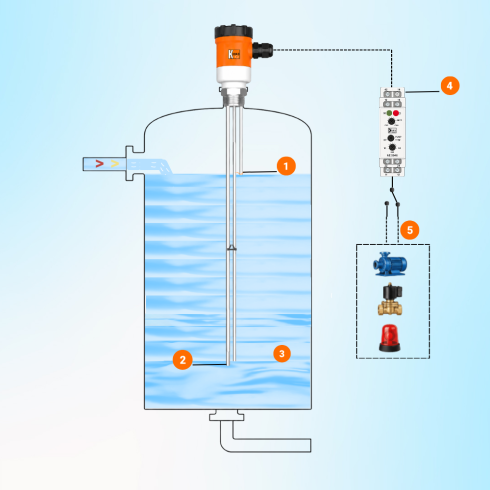
KOBOLD describes the principle simply: the switch detects whether a conductive liquid bridges a sensing electrode and a reference electrode, or a conductive unlined metal tank wall. Because it only detects a point, it gives alarms and pump commands rather than a continuous level value.
How a Conductive Level Switch Works
Omron explains that the controller compares the resistance between the electrodes with an internal reference resistance. When the liquid touches the electrodes, the measured resistance falls below that reference and the relay operates.
The output of a conductive level switch is usually a changeover relay contact that drives a pump contactor, a solenoid valve or an alarm input. Contact ratings and coil behaviour follow the rules in electromagnetic relay working and coil suppression.
KOBOLD notes that the controller uses a low alternating voltage because it reduces polarisation, electrolysis and oxidation of the electrodes. A DC signal would slowly eat one rod and coat the other.
Why AC Excitation Is Used
If DC flowed through the liquid, one electrode would act as an anode and the other as a cathode, as in an electrolysis cell. Metal would dissolve from one rod, gas and scale would build on the other, and the switching point would drift.
An alternating signal reverses direction many times every second, so these effects largely cancel. The Omron 61F general purpose type uses 8 V AC between the electrodes, a level that is low enough to be safe for operators touching a probe holder.
Never connect a conductive probe directly to a PLC DC input to save a relay. Use a proper electrode relay so the liquid only ever sees a low AC signal.
Sensitivity, Resistance and Conductivity
The sensitivity of an electrode relay is set in kΩ: the relay operates when the liquid path resistance falls below its operate value. Resistance depends on liquid conductivity and electrode geometry, the same cell constant idea used in a conductivity sensor.
R = resistance between electrodes
K = effective cell constant of the electrode pair, per cm
κ = liquid conductivity
Example:
K = 1 per cm, κ = 20 µS/cm = 0.00002 S/cm
R = 1 ÷ 0.00002
R = 50000 Ω = 50 kΩ
Real tank electrodes are far apart and have a different effective constant, so treat this only as a guide and measure the actual resistance during commissioning. The example shows why low conductivity liquids need a high sensitivity relay.
| Omron 61F Type | Operate Resistance | Release Resistance | Suits |
|---|---|---|---|
| General purpose | 0 to about 4 kΩ | About 15 kΩ to infinity | Purified water, sewage |
| High sensitivity | About 15 to 70 kΩ | About 300 kΩ to infinity | Distilled and high resistivity water |
| Low sensitivity | 0 to about 1.8 kΩ | About 5 kΩ to infinity | Salt water, sewage, acids, alkalis |
| Long distance 4 km | 0 to 0.7 kΩ | 2.5 kΩ to infinity | Remote tanks on long cables |
The gap between operate and release resistance acts as hysteresis, which stops chatter as ripples touch the rod. Omron also lists an operate time of 80 ms and a release time of 160 ms for these controllers.
Conductive Level Switch Sensitivity Selection
KOBOLD gives a selection guideline of more than 20 µS/cm for the liquid. Oils, fuels, most organic solvents and highly purified or deionised water are generally unsuitable, because they cannot carry enough current.
For such liquids, choose a capacitance level switch or a vibrating fork level switch. A conductive level switch on diesel or transformer oil simply never operates.
Set the sensitivity only as high as you need, not at maximum. Too much sensitivity lets condensation films and wet deposits on the holder hold the relay in after the level falls.
Multi Electrode High and Low Pump Control
Omron describes a three electrode method. E1 is the long level detection rod for the upper point, E2 is the self holding rod for the lower point, and E3 is the common electrode, which is the longest rod or the metal tank wall.
When the liquid reaches E1, relay X operates, and its own contact connects E1 to E2. The relay then stays on while the level falls, until the liquid leaves E2, so the pump runs between two clear points without chatter.
Two electrodes or one rod plus tank wall.
High, low and common rods with self holding.
Four or more rods in one holder.
For a supply tank, the relay starts the pump when the level leaves E2 and stops it at E1, while a drainage sump uses the reverse logic. The same seal in idea appears in ladder logic start and stop circuits.
Omron points out that without the self holding circuit, ripples on the surface make a two electrode relay switch on and off rapidly. The third electrode gives a deadband that protects both pump and contactor.
Pump Cycle Formula Between Electrodes
The vertical gap between the high and low electrodes decides how often the pump starts. A larger gap means fewer starts per hour, which protects the motor and contactor.
Fill time = V ÷ Qin, pump run time = V ÷ (Qpump minus Qin)
Example:
D = 2 m, H = 0.5 m, Qin = 6 m³/h, Qpump = 15 m³/h
V = 0.7854 × 4 × 0.5 = 1.57 m³
Fill = 1.57 ÷ 6 × 60 = 15.7 min
Run = 1.57 ÷ 9 × 60 = 10.5 min
Starts per hour = 60 ÷ 26.2 = 2.3
Electrode Spacing and Pump Start Calculator
Compare the result with the allowed starts per hour on the motor data and the starter type, as covered in DOL vs star delta starter. If the starts are too many, increase the electrode gap or the tank area.
Second Worked Example: A Small Sump
A drainage sump is 1.2 m in diameter with 3 m³/h inflow and a 10 m³/h pump. With a 0.3 m gap, V = 0.7854 × 1.44 × 0.3 = 0.34 m³, fill time is 6.8 min and run time is 2.9 min.
That gives about 6.2 starts per hour, which may be too many for a small submersible pump. Raising the gap to 0.6 m halves the starts to about 3.1 per hour.
6 Practical Steps to Install a Conductive Level Switch
KOBOLD notes that a reference electrode is required in non conductive tanks made of plastic or concrete. In lined vessels for acids, check rod material as in level measurement in corrosive chemicals.
Omron gives maximum cable lengths of 1 km for its general purpose type and only 50 m for the high sensitivity type, using 0.75 mm² three core cable. Long cables add capacitance that looks like a wet probe to a sensitive relay.
Electrode Materials and Ratings
KOBOLD offers electrodes in stainless steel, titanium or Hastelloy, chosen to suit the medium, with ratings up to 30 bar and up to 150 °C depending on the model. Rigid rods, suspended cable electrodes and cut to length versions cover shallow tanks to deep wells.
Insulated rods with only a short bare tip reduce false switching from wet deposits on the holder. Coastal water, chlorinated water and effluent may need titanium, much like the material choices in conductivity sensor cell constant calibration work.
- No moving parts in the tank.
- Low cost for many switching points in one holder.
- Simple relay logic for fill and empty control.
- Works in pressurised and hot vessels with suitable probes.
- Fails on oils, fuels, solvents and deionised water.
- Conductive deposits or foam can cause false switching.
- Scale and crystals can insulate the rods.
- Point detection only, no continuous level.
Applications in Water and Process Plants
For pump protection on suction tanks, a dry run electrode trips the motor before the liquid falls below the suction pipe. Pump types and their dry run sensitivity are compared in centrifugal vs positive displacement pump.
Conductive Level Switch Troubleshooting
- Measure liquid conductivity with a portable meter.
- Check probe resistance wet and dry with the relay disconnected.
- Clean scale, oil films and deposits from rods and holder.
- Confirm the common electrode or tank earth connection.
- Verify cable length and insulation resistance.
- Check the sensitivity setting against the liquid.
- Simulate each point and confirm relay and pump action.
A conductive level switch relay that never drops usually means a wet deposit bridging the holder or excessive sensitivity. A relay that never operates often means a broken common connection or an oily film on the rods, which is a frequent cause when a float level switch is replaced by conductive probes.
Omron 61F Floatless Level Switch Datasheet
Conductive Probe Level Monitoring Video
Conductive Level Switch FAQ
It is a point level sensor that detects a conductive liquid when the liquid bridges two electrodes or an electrode and an earthed tank wall. An electrode relay senses the low resistance and switches its output contact.
It has no moving parts inside the tank. That makes it popular for water tanks, sumps and pump control in buildings and plants.
A DC current through the liquid of a conductive level switch would cause electrolysis, eroding one electrode and coating the other. The switching point would then drift and the rods would fail early.
AC reverses direction many times a second, so these effects largely cancel. KOBOLD notes that this reduces polarisation, electrolysis and oxidation of the electrodes.
No, oils, fuels and most organic solvents do not conduct enough current to operate a conductive level switch relay. KOBOLD gives a guideline of more than 20 µS/cm for suitable liquids.
Use a capacitance, vibrating fork or float switch for such products. Highly purified or deionised water is also unsuitable for a standard electrode relay.
The long common rod stays wet, the low rod sets the lower point and the high rod sets the upper point. When the liquid reaches the high rod, the relay operates and latches through its own contact.
It drops out only when the liquid leaves the low rod. The pump therefore runs between two fixed points without chattering on surface ripples.
Choose the lowest sensitivity that reliably operates the conductive level switch on your liquid. Omron offers general purpose, high sensitivity and low sensitivity types for ordinary water, distilled water and salt water respectively.
Too high a setting lets deposits and condensation keep the relay energised. Too low a setting can miss weak, dilute liquids altogether during normal operation.
Omron lists up to 1 km for its general purpose relay with 0.75 mm² three core cable. The high sensitivity type is limited to about 50 m.
Long cables add capacitance that a sensitive relay can read as a wet probe. Long distance models with lower operate resistance are made for remote tanks and distant borewells.
A conductive film of scale, sludge or condensation on the holder can bridge the rods of a conductive level switch. Excessive sensitivity makes this problem very much worse in dirty water.
Clean the rods and holder, then reduce the sensitivity setting. Rods insulated except for a short bare tip also help in dirty or foaming liquids.
Related Articles
- Level Switch Selection Guide
- Float Level Switch Working Principle
- Capacitance Level Switch Working
- Vibrating Fork Level Switch Working
- Conductivity Sensor Working
External References
- 61F G Floatless Level Switch Datasheet, Omron
- Conductive Level Monitoring, KOBOLD Messring
- Level Sensor, Wikipedia
What We Learn Today
- A conductive level switch detects conductive liquids when they bridge electrodes, and KOBOLD suggests more than 20 µS/cm for reliable operation.
- Electrode relays use low AC excitation, such as 8 V AC on the Omron 61F, to avoid electrolysis, polarisation and erosion of the rods.
- Three electrode control uses a self holding relay, so the pump runs between the high and low rods without chattering on ripples.
