
When instrument air fails, a spring return actuator drives its valve fully open or fully shut, and some processes cannot tolerate either. A small pneumatic relay can trap the air already in the actuator and keep the valve exactly where it was.
A lock up valve sits between the positioner and the actuator and closes the moment supply air drops below its trip point. The valve then holds its last position until the air system recovers and an operator resets the loop.
What Is a Lock Up Valve?
A lock up valve is a pneumatic relay that blocks the air line between a positioner and an actuator when the supply air pressure falls below a preset value, so the actuator keeps its trapped air and the control valve stays in its last position. In the language of fail open, fail closed and fail locked valves, it is the device that creates the fail locked action.
It is also called a lock up relay, air lock relay, position lock or fail freeze valve. Whatever the name, it is an accessory on the actuator, much like the valve positioner and the filter regulator that feed it.
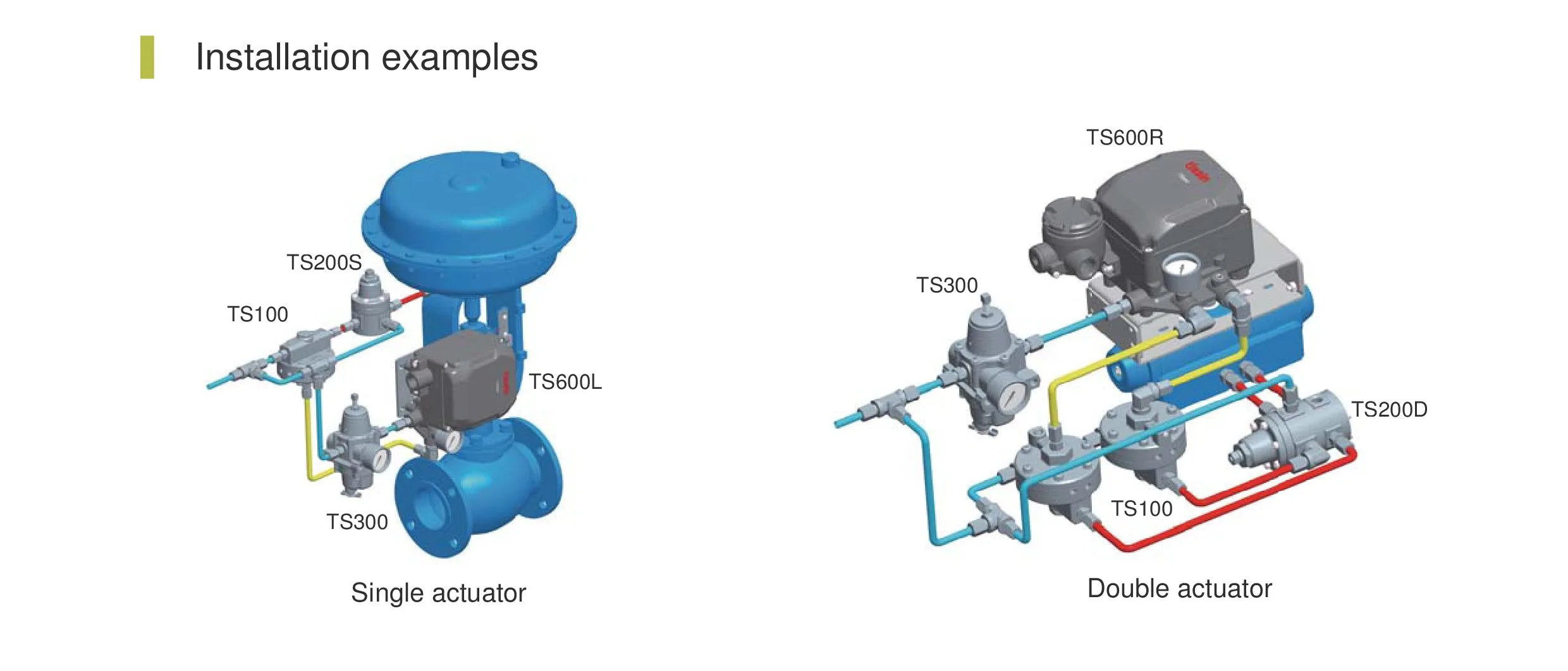
Automation Forum explains that supply air acts on a diaphragm against a spring, and while the air force is higher the positioner signal passes straight to the actuator. When supply drops below the adjusted value, the spring wins and pushes the plug into its seat, trapping the actuator pressure.
Why Plants Need Fail in Place Action
A spring return actuator gives a clear fail open or fail closed position, which suits most loops. Some services, however, are better served if the valve simply stays put, because a sudden swing to either end would upset the process far more than a steady last position.
A boiler feedwater valve, a fuel gas control valve to a furnace or a compressor anti surge valve are typical examples. Double acting piston actuators, explained in diaphragm actuator vs piston actuator, have no spring at all, so a lock up relay on each cylinder port is the only reliable way to hold them.
The Control.com textbook on valve failure modes notes that a pneumatic valve can fail locked only if an external device traps fluid pressure in the actuator chamber. Without such a device, a springless piston actuator may drift under unbalanced plug forces.
How a Lock Up Valve Works Inside
The adjusting screw sets spring compression and therefore the trip pressure. Many designs reset automatically when supply recovers, while some, such as the Azbil three way lock up relay, also offer a manual reset lever for interlock duties linked to an emergency shutdown system.
Samson describes its Type 3709 as shutting off the signal pressure line either when the air supply falls below an adjusted value or fails completely. Its data sheet lists a switching accuracy of about 0.2 bar at a 2 bar set point and about 0.4 bar at a 6 bar set point.
Always mount the lock up valve as close to the actuator as possible, with short rigid tubing. Every extra metre of tube adds volume and fittings that can leak once the air is trapped.
Lock Up Valve Types and Configurations
One supply port and one output path for a spring return diaphragm actuator.
Two output paths closed together for both cylinder ports of a piston actuator.
High capacity passages, often used with volume boosters on large actuators.
Emerson builds the Fisher 377 trip valve in three main modes: the 377D fails the piston down, the 377U fails it up and the 377L locks it in its last position. The D and U versions need a volume tank to stroke the piston, while the 377L needs no volume tank.
Lock Up Valve Versus Spring Return Fail Safe
| Feature | Spring Return Fail Safe | Lock Up Relay Action |
|---|---|---|
| Position on air loss | Fully open or fully closed | Last position before failure |
| Extra hardware | None, spring is built in | Relay, fittings, sometimes volume tank |
| Holding time | Unlimited, spring always acts | Limited by leakage of trapped air |
| Typical actuator | Spring diaphragm | Piston or spring diaphragm |
| Safety logic | Simple, energy free | Needs testing and leak control |
The spring is a passive device and never needs air, which is why most safety valves use it. The trapped air of this relay is only as good as the tightness of the tubing, the actuator seals and the pneumatic manifold fittings.
Never treat fail last position as a safety function by default. If the hazard study says a valve must close on loss of air, a spring or a dedicated trip system is required, as discussed in SIS and BPCS differences.
Trip Pressure Setting Rules
The trip point must be high enough that the relay closes while the actuator still has enough pressure to hold its load. It must also be low enough that normal dips in the air header do not cause nuisance locking.
For the Fisher 377, the Emerson manual allows a trip point from a minimum of 2.8 bar up to 72 percent of supply pressure. It resets at 12.5 to 33 percent above the adjusted trip point, and supply must stay between 3.8 and 10.3 bar.
Hold Time Formula for Trapped Air
Once the relay closes, any leak from the actuator, tubing or solenoid valve lets the trapped pressure fall. With ideal gas behaviour at constant temperature, the time to lose a given pressure depends on the trapped volume and the leak rate.
V = trapped volume of actuator chamber and tubing, litres
ΔP = allowed pressure drop before the valve moves noticeably, bar
Pa = atmospheric pressure, 1.01325 bar
Q = leak rate in normal litres per minute
Example:
V = 10 L, ΔP = 0.3 bar, Q = 0.05 NL/min
Pa × Q = 1.01325 × 0.05 = 0.0507
t = 10 × 0.3 ÷ 0.0507 = 59.2 min
Lock Up Valve Hold Time Calculator
Second Worked Example: Choosing a Trip Point
A refinery header normally runs at 6 to 7 bar, and the filter regulator feeds the positioner at 5.5 bar. The actuator needs 3.0 bar to hold the valve against process forces at maximum travel.
With a Fisher 377 style relay, the maximum trip point is 0.72 × 5.5 = 3.96 bar, so a setting of 3.8 bar keeps a margin above 3.0 bar. The reset then falls between 3.8 × 1.125 = 4.28 bar and 3.8 × 1.33 = 5.05 bar, which is safely below the 5.5 bar normal supply.
Write the trip and reset pressures on a tag fixed to the relay and in the instrument data sheet. Future technicians then know the design value instead of guessing from the screw position.
7 Proven Steps to Install and Set a Lock Up Valve
Automation Forum recommends a gauge showing actual diaphragm pressure on diaphragm actuators and a gauge on the reserve tank for piston actuators. Good supply air quality also matters, so keep moisture away as explained in dew point in instrument air.
Testing and Maintenance in the Field
The Emerson manual gives a simple periodic check: isolate the valve from the loop, watch the supply gauge and reduce supply slowly until the valve trips. Then raise supply and confirm the reset happens 12.5 to 33 percent above the trip point.
- Valve isolated from the process or loop in manual with permit.
- Supply gauge and actuator gauge calibrated and readable.
- Trip pressure within the tolerance on the data sheet.
- Reset pressure recorded and below normal supply.
- Valve position held steady after the trip.
- Pressure decay over 10 minutes recorded.
- Tubing and fittings soap tested for leaks.
- Results entered in the maintenance record.
If the valve drifts quickly, check the actuator diaphragm, piston seals and every tube fitting before blaming the relay. A combined approach with a partial stroke test plan helps find sticking valves before a real air failure exposes them.
Troubleshooting a Lock Up Valve
A slow stroke after fitting the relay is a common complaint on large actuators. Compare the relay Cv with the positioner and booster capacity, and check the general causes in control valve troubleshooting.
Double acting lock up versions close both cylinder ports at the same time. Samson routes the control pressure through a capillary tube to both spring systems so both plugs open and close together.
- Keeps the process steady during short air failures.
- Holds springless piston actuators in place.
- Simple, low cost and fully pneumatic.
- Can combine with trip valves and volume tanks.
- Holding time limited by leakage.
- Not a safety function on its own.
- Adds fittings and a possible failure point.
- Needs periodic trip and leak testing.
During commissioning, simulate air failure by closing the supply isolation valve, not by venting the positioner. Venting the positioner tests the wrong path and gives a false pass.
Samson Type 3709 Lock Up Valve Data Sheet
Air Lock Relay Demonstration Video
Lock Up Valve FAQ
It blocks the air line between the positioner and the actuator when supply pressure falls below a set value. The air trapped in the actuator then holds the control valve in its last position.
When supply recovers above the reset point, the air path opens again. The positioner then resumes normal control of the valve without any manual action on most models.
It sits between the positioner output and the actuator, as close to the actuator as practical. The sensing port takes air from the same supply that feeds the positioner.
Short rigid stainless steel tubing keeps the trapped volume small and reduces leak points. A gauge on the actuator pressure helps a great deal during testing and fault finding.
The trip point must be above the pressure the actuator needs to hold its load. It must also be below the lowest normal supply pressure to avoid nuisance locking.
Emerson allows the Fisher 377 trip point from 2.8 bar up to 72 percent of supply. Always follow the data sheet of the exact model you are using.
Hold time depends on the trapped volume, the allowed pressure drop and the leak rate. A 10 litre volume leaking 0.05 normal litres per minute loses 0.3 bar in about an hour.
Tight fittings and good actuator seals extend this time greatly. Measure the real pressure decay during commissioning instead of assuming a value from a data sheet.
Not automatically, because the right fail position depends on the process hazard. Many shutdown valves must close fully, so they rely on springs or dedicated trip systems.
Fail last position suits services where a sudden movement is worse than a steady valve. The hazard study and the valve data sheet must both confirm this choice in writing.
A volume tank stores air so a trip valve can drive a springless piston to a fixed end position. Emerson states the Fisher 377D and 377U need one, while the 377L lock mode does not.
For pure fail locked duty, both cylinder ports are simply closed together. The tank is still useful if the design later needs a fail open or fail closed stroke.
Test it at commissioning and then at the interval set by the maintenance plan, often during scheduled shutdowns. Critical services may need more frequent checks during the run.
Each test should record the trip point, the reset point and the pressure decay over a fixed time. Rising leakage over several tests shows seals that need replacement soon.
Related Articles
- Fail Safe Valve Position: Fail Open, Fail Closed, Fail Locked
- Control Valve Positioner Working
- Diaphragm Actuator vs Piston Actuator
- Partial Stroke Testing of ESD Valves
- Control Valve Troubleshooting
External References
- Type 3709 Pneumatic Lock Up Valve Data Sheet, Samson
- Control Valve Air Lock, Automation Forum
- Control Valve, Wikipedia
What We Learn Today
- A lock up valve senses supply air pressure and traps the air in the actuator when supply falls below its trip point, holding the valve in place.
- The trip point must sit above the actuator holding pressure and below normal supply, and the reset point is set higher to avoid chattering.
- Hold time depends on trapped volume, allowed pressure drop and leak rate, so commissioning must include a measured pressure decay test.
