A flow switch only protects a pump or a cooler if its trip point sits in the right place between normal flow and damaging flow. This page shows how to pick that number, convert it to the units on the switch and prove it works.
A flow switch setpoint is the flow at which the contact changes state, chosen between normal flow and the minimum safe flow. Learn how to pick it, convert velocity to m³/h, adjust paddle, thermal and DP switches and test the trip.
How to set a flow switch setpoint correctly?
Flow switch setpoint is the flow at which the contact changes state, placed between normal flow and the minimum safe flow, ideally at least 25 % below the low end of normal flow as Gems Sensors advises. For example, 0.3 m/s in a 52.5 mm ID pipe gives Q = v × A × 3600 = 2.34 m³/h, or 46.8 % of a 5 m³/h normal flow.
- Find minimum normal and minimum safe flow
- Place the trip 25 % below normal, above safe flow
- Convert to velocity, paddle setting or DP
- Adjust on real flow and read the trip on falling flow
- Record as found and as left values
What Is a Flow Switch Setpoint?
A flow switch setpoint is the flow rate, velocity or differential pressure at which a flow switch changes its contact or output state. It is usually set below normal flow so the switch raises a low flow alarm or trips a pump before the process reaches a damaging flow.
- Gems Sensors advises a setpoint at least 25 % below the low end of the normal flow range
- Most switches trip on falling flow and reset only after flow rises past the deadband
- Paddle switches are set by paddle length and a range screw, thermal switches by teach buttons or a magnet
- Setpoint flow in m³/h = velocity × pipe area × 3600
- Always prove the trip with a real flow reduction, not only by moving the paddle by hand
If you need a refresher on how the three common designs sense flow, read our flow switch working principle for paddle, DP and thermal types first. This article is its practical companion and focuses only on where to set the trip and how to prove it.
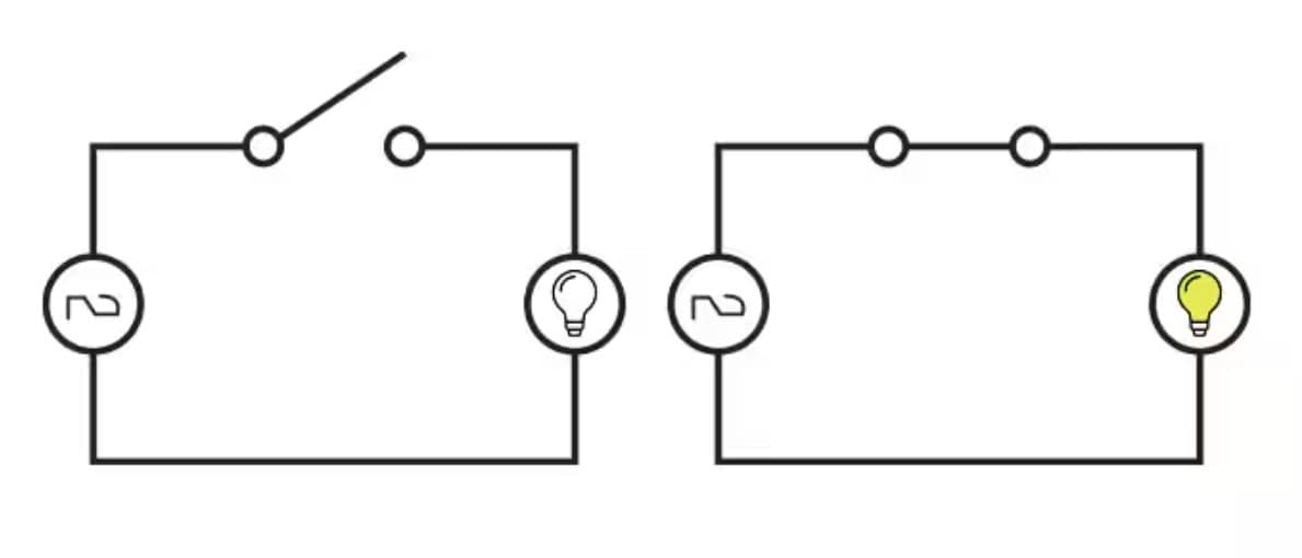
Low Flow Alarm vs Pump Protection Trip
First decide what the switch protects. A low flow alarm warns the operator, while a protection trip stops a pump or heater before damage occurs.
- Warns the operator, process keeps running
- Set closer to normal flow for early warning
- Short time delay is acceptable
- Managed under alarm rationalisation rules
- Stops a pump, heater or burner automatically
- Set just above the damaging flow with margin
- Needs a proven, tested trip path
- May fall under a safety function review
For alarms, follow the rationalisation ideas in alarm management to ISA 18.2 so the alarm is meaningful and not a nuisance. For trips, the chosen flow switch setpoint must sit above the minimum continuous flow given on the pump datasheet, which our page on centrifugal vs positive displacement pumps helps you read.
A centrifugal pump running near shut off heats the liquid in its casing, as this centrifugal pump working principle guide explains. A minimum flow switch is often its cheapest protection.
How to Choose the Flow Switch Setpoint
Place the trip between minimum normal flow and minimum safe flow, leaving room for switch accuracy.
% = Setpoint flow ÷ Normal flow × 100
Gems guideline: % ≤ 75 % of the low end of normal
Lower limit: setpoint × (1 + accuracy) above damaging flow
Write both the normal flow and the minimum safe flow on the instrument datasheet next to the flow switch setpoint. Six months later nobody will remember why 46 % was chosen unless the reason is written down.
Velocity to m³/h: Converting the Trip Point
Thermal dispersion switches are usually specified in velocity, such as cm/s or m/s, while process datasheets give flow in m³/h or L/min. To convert, you need the pipe internal diameter, not the nominal size, because a 2 inch Schedule 40 pipe has an ID of about 52.5 mm.
Flow Q (m³/h) = v (m/s) × A × 3600
Velocity v = Q ÷ (A × 3600)
The same relationship sits behind our flow rate formula guide, and you can cross check a result with this pipe flow velocity calculator. Use the calculator below to turn a velocity setpoint into a flow and see how it compares with normal flow.
A = 3.1416 × 0.0525² ÷ 4
A = 0.002165 m²
Q = 0.3 × 0.002165 × 3600
Q = 2.34 m³/h, about 39 L/min
Normal flow 5 m³/h, so setpoint = 46.8 % of normal
For a DP flow switch across an orifice, remember that differential pressure varies with the square of flow. A trip at 50 % of normal flow therefore needs a DP setting of only 25 % of normal DP, which is a common mistake on site.
ΔP_set = ΔP_normal × (Q_set ÷ Q_normal)²
Example: 40 mbar at normal flow, trip at 50 %
ΔP_set = 40 × 0.5² = 10 mbar
Paddle, Thermal and DP Switch Setpoint Methods
Each switch type is set differently: paddles by length and spring force, thermal switches by a taught velocity and DP switches by a pressure setting.
Paddle trimmed to pipe size, then a range screw sets spring force.
Velocity set by teach buttons, magnet or IO Link.
Set as DP across an orifice or filter.
Fixed by piston and spring, often factory set.
For DP switches the adjustment is the same as on a pressure switch, so our article on differential pressure switch working and our guide to pressure switch setpoint and deadband configuration apply directly. Thermal switches behave like a simplified thermal mass flow meter with a single output.
| Pipe Size (inch) | Paddle Length (mm) | Actuate, min setting (GPM) | Deactuate, min setting (GPM) |
|---|---|---|---|
| 1 | 34 | 4.0 | 1.8 |
| 1½ | 57 | 7.0 | 4.0 |
| 2 | 57 | 14.1 | 9.7 |
| 3 | 88 | 27.7 | 25.1 |
| 4 | 88 | 59.4 | 52.8 |
| 6 | 167 | 75.7 | 52.8 |
What Is Flow Switch Hysteresis?
Hysteresis, also called deadband or differential, is the gap between the flow that operates the contact and the flow that resets it. It stops the contact chattering when flow hovers around the trip, in the same way a Schmitt trigger cleans up a noisy electronic signal.
Our article on deadband in pressure switches explains the same idea with numbers, and electronic switches often let you set the reset point separately.
For a flow proven permissive at pump start, add a start up bypass timer in the PLC. Flow takes a few seconds to build, so without a timer the trip logic stops the pump before it has had a chance to deliver.
How to Adjust a Flow Switch
Set the real flow to the trip value, then change the screw or teach setting until the output just changes.
Dwyer says its TDFS2 learns a setpoint when you tap a target three times with the supplied magnet. The ifm SI series instead teaches a high point at normal flow and a low point at minimum flow with its arrow buttons.
Installation decides whether any flow switch setpoint will repeat. Dwyer asks for at least 12 pipe diameters upstream and 5 downstream for the TDFS2, with the probe inserted 10 to 25 % of the pipe ID, while the FS 2 paddle needs about 5 diameters clear of elbows, valves and pumps.
Dwyer quotes a repeatability of 0.02 m/s plus 3 % of setpoint for its TDFS2 thermal dispersion flow switch. At a 0.3 m/s setting that is about 0.03 m/s, which shows why tiny velocity settings are hard to repeat.
On a paddle switch the flow switch setpoint shifts if the paddle is bent or trimmed too short. Keep the spare paddle layers, since DwyerOmega uses them to reinforce the vane.
How to Test a Flow Switch
A proper test proves the flow switch setpoint and the whole loop, from sensor to PLC input to final element. Moving the paddle by hand only proves the microswitch, so always reduce the real flow where the process allows it.
- Reference flow meter or calibrated clamp on meter available
- Trip direction confirmed: falling, rising or both
- Trip value read on falling flow for a low flow switch
- PLC input, alarm text and trip action confirmed
- As found and as left values logged with date and tag
The routine is close to the one in our pressure switch calibration steps, with flow taking the place of pressure. Check contact use against our NO and NC switch wiring guide, since a protection trip should normally be wired fail safe so a broken wire causes a trip.
If you set a DP flow switch across a filter or a long pipe run, estimate the expected DP first with our pipe pressure drop calculator.
Flow Switch Setpoint Troubleshooting
Most faults come from a trip too close to normal flow, poor installation or ignoring the DP square law.
| Symptom | Likely Cause | Fix |
|---|---|---|
| Trips at normal flow | Setpoint too close to normal, or reading rising value | Lower trip, check falling flow value |
| Never trips on low flow | Paddle too short or bent, range screw at max | Trim to the correct length, reset screw |
| Chatters around the trip | Turbulence near elbow or valve, small deadband | Move switch, add PLC time delay |
| Thermal switch drifts | Fluid temperature or composition changed | Reteach at current conditions |
| DP switch trips late | DP set linearly, not by flow squared | Recalculate with the square law |
Dwyer adds that changes in fluid temperature, density or viscosity, and the zone between laminar and turbulent flow, shift thermal switch settings.
Flow Switch Setpoint FAQ
Set the trip at least 25 percent below the low end of normal flow, as Gems Sensors advises, while keeping it above the minimum safe flow of the pump. For example, with 5 m³/h normal flow, a trip near 2.3 m³/h leaves a good margin.
Multiply the velocity in m/s by the pipe internal area and by 3600 to get m³/h. For example, 0.3 m/s in a 52.5 mm ID pipe gives 0.3 × 0.002165 × 3600, which is about 2.34 m³/h.
Always use the internal diameter, not the nominal pipe size.
The setpoint is the flow at which the contact changes state, while the reset point is where it returns. The gap is the deadband, and on a DwyerOmega FS 2 in a 1 inch pipe it runs from 4.0 GPM rising to 1.8 GPM falling.
Trim the paddle to the length the manual gives for your pipe size, then turn the range screw. On the DwyerOmega FS 2, fully tightening the bolt gives the minimum flow setting.
Set the real flow to the trip value, adjust until the contact just changes and confirm it again on falling flow.
The usual causes are a setpoint too close to normal flow, turbulence from a nearby elbow or valve, or air bubbles at the sensor. A bent paddle or a dirty thermal probe also shifts the trip.
Check the real flow when it trips, then add straight pipe, a short PLC delay or a lower setting.
Thermal dispersion switches suit low flows and clean liquids because they have no moving parts, while DP switches suit gas, steam and dirty service. Paddle switches remain the simple choice for water and cooling lines from about 1 inch upward.
The ifm manual notes oil needs 2 to 3 times the water velocity on thermal switches.
Related Articles
- Flow Switch Working Principle: Paddle, DP and Thermal
- Pressure Switch Setpoint and Deadband Configuration
- Differential Pressure Switch Working
- Deadband in Pressure Switches
- Thermal Mass Flow Meter Working
External References
- DwyerOmega FS 2 Flow Switch Manual
- Gems Sensors: How to Select a Liquid Flow Switch
- Wikipedia: Flow measurement
What We Learn Today
- How to choose a flow switch setpoint between normal flow and damaging flow, allowing for switch accuracy, deadband and the trip direction.
- How to convert a velocity setting in m/s into m³/h from pipe internal diameter, and why a DP switch setting follows the square of flow.
- How to adjust paddle, thermal dispersion and DP flow switches, test the trip on falling flow and fix chattering, drift and late trips.