An instrument air header that is too small starves valves at the far end of the plant, while one that is too big wastes money and holds wet air. Here you will size the header, branches and receiver with simple rules and a worked example.
Learn how to add up instrument air users, apply margins, pick header and branch sizes from velocity and pressure drop, and size the receiver. A solved example and a pipe ID calculator make the method easy to repeat.
How is instrument air header sizing done for a process plant?
Instrument air header sizing is done by adding up the peak air demand of all users, converting it to actual flow at minimum line pressure and choosing a pipe that keeps velocity near 6 m/s. Use ID = √(4Q ÷ πv). For example, 300 Nm³/h at 7 barg is 37.93 m³/h actual, which needs a 47.3 mm minimum ID, so a 2 inch pipe is chosen.
- List every air user with steady and stroking consumption
- Add margins for leakage and future users
- Convert free air flow to actual flow at minimum line pressure
- Calculate pipe ID for about 6 m/s and pick the next standard size
- Check pressure drop to the farthest user and size the receiver
What Is Instrument Air Header Sizing?
Instrument air header sizing is the process of choosing the diameter of the main air pipe and its branches so every pneumatic instrument gets clean, dry air at the required pressure under peak demand. It starts with adding up the air users, then selects the pipe size that keeps velocity and pressure drop within safe limits.
- Add the steady and intermittent consumption of every user in Nm³/h
- Add margins for leakage and future users
- Convert to actual flow at line pressure
- Size the header for about 6 m/s or less and a small total pressure drop
- Size the receiver to ride through a compressor trip
The first number you need is the total air demand, which our instrument air consumption calculation covers user by user. Instrument air header sizing then turns that demand into pipe diameters, branch sizes and a receiver volume.
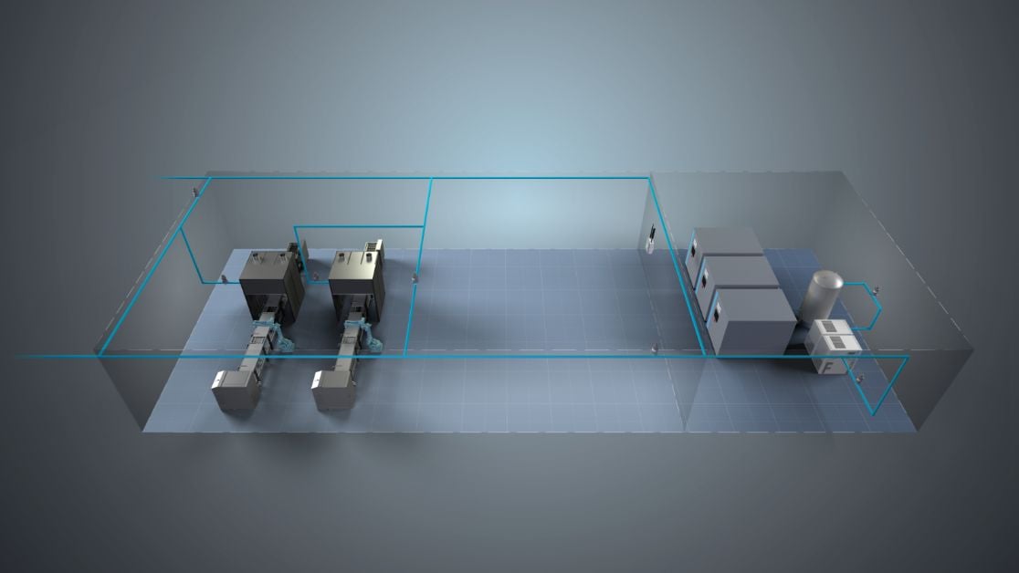
Instrument air must also meet a quality standard, and ISA 7.0.01 sets the pressure dew point at least 10 °C below the lowest ambient temperature seen by any part of the system. Our article on dew point risks in instrument air explains what happens when moisture reaches positioners.
Step 1: Consumer Load Summation and Diversity
List every user from the instrument index and the P&ID, and give each one a steady consumption and, where it applies, a stroking consumption. Positioners bleed air all the time, while on and off valves only use air when they move, which our page on the control valve positioner explains.
Positioners, I to P converters and pneumatic controllers that consume air all the time.
On and off valves, shutdown valves and dampers that use air only when stroking.
Bubbler level purge, panel purge and analyser houses with fixed flow.
Leakage and future users added on top of the connected load.
Diversity means not every intermittent valve strokes at the same moment, so the peak is lower than the sum of all stroke volumes. Purge users such as bubbler level purge run all the time, so they never get a diversity reduction.
| User Group (example values) | Quantity | Air Each (Nm³/h) | Total (Nm³/h) |
|---|---|---|---|
| Control valves with positioners | 120 | 1.0 | 120 |
| On and off valves, averaged | 40 | 2.0 | 80 |
| Analysers and purge | lot | 50 | 50 |
| Connected load | 250 | ||
| Plus 20 % leakage and future | 300 |
The numbers in this table are example values for teaching only. Always use the air consumption figures from each positioner or actuator data sheet, because modern low bleed positioners use far less air than older designs.
Atlas Copco notes that velocities above 9 m/s can carry water and debris along the pipe. That is why instrument air header sizing aims for lower velocity than many process gas lines.
Step 2: Convert to Actual Flow at Line Pressure
Load lists are written in normal or free air units, but the pipe sees compressed air at line pressure, which takes up much less volume. Our page on actual flow, standard flow and normal flow explains the conversion in detail.
Pa = 1.013 bar, P = 7 barg
Actual = 300 × 1.013 ÷ 8.013
Actual = 37.93 m³/h
Here we treat compression as isothermal, which is fine because the air cools to near ambient after the aftercooler and dryer. Use the minimum header pressure, not the compressor discharge, so the size works when pressure sags.
What Is the Recommended Velocity in Compressed Air Piping?
Atlas Copco quotes the British Compressed Air Society advice that a velocity of 6 m/s or less stops moisture and debris being carried past drain legs into controls. It recommends 6 to 7 m/s for main headers and never more than 9 m/s, so instrument air header sizing usually targets 6 m/s.
Q = 37.93 m³/h = 0.01054 m³/s
v = 6 m/s
ID = 47.3 mm
Choose 2 in Sch 40, ID 52.5 mm, v = 4.87 m/s
Pick the next standard pipe size above the calculated ID and then check the real velocity. You can cross check the velocity with this pipe flow velocity calculator when you test other sizes.
| Pipe Size (Sch 40) | Internal Diameter | Capacity at 6 m/s, 7 barg |
|---|---|---|
| 1/2 in | 15.8 mm | 33 Nm³/h |
| 3/4 in | 20.9 mm | 59 Nm³/h |
| 1 in | 26.6 mm | 95 Nm³/h |
| 1 1/2 in | 40.9 mm | 224 Nm³/h |
| 2 in | 52.5 mm | 370 Nm³/h |
| 3 in | 77.9 mm | 814 Nm³/h |
These capacities come straight from the same formula, so you can use the table to pick branch sizes quickly. Most plant branches fall between 1/2 in and 2 in, while the final drops to instruments are usually tubing through an instrument air filter regulator.
Step 3: Check Pressure Drop in Header and Branches
Atlas Copco recommends that the pressure drop from the compressor to the most remote user stays at or below 0.1 bar in the fixed pipe network. Hoses, couplings and fittings add more on top, so check the full path with our guide to pressure drop in pipes.
Atlas Copco points out that losses in flexible hoses, couplings and fittings are often larger than the loss in the fixed pipe itself.
For the pressure drop check you need friction factor, which depends on the Reynolds number of the flow. In long headers, length often decides the size more than velocity, so run both checks.
Ring Main vs Dead End: Which Layout Is Better?
Atlas Copco calls a closed ring around the consumption area the preferred layout, with branches running from the loop to each user. For instrument air header sizing in a ring, many engineers size each half of the loop for the full flow, which gives a safe result if one side is isolated.
- Air reaches each user from two directions
- Smaller pressure drop at far users
- A section can be isolated and others stay live
- Preferred by Atlas Copco for large areas
- Simple and cheaper for small plants
- Far users see the largest drop
- A single break isolates everything downstream
- Water collects at the dead end
Header Installation Rules: Take Offs, Isolation and Slope
A good header takes every branch from the top, slopes toward drain legs and has isolation valves for each area.
Local distribution manifolds keep tubing runs short and make hook up drawings simple, as shown in our instrument hook up drawing guide.
How to Size an Air Receiver for Instrument Air
The receiver stores air so instruments keep working for a set hold up time after a compressor trip, letting valves move to a safe position in a controlled way. An air receiver is a pressure vessel, so its design also follows the rules in this guide to pressure vessel basics.
t = 10 min, C = 5 Nm³/min (300 Nm³/h)
P1 = 7 barg, P2 = 4.5 barg
V = 10 × 5 × 1.013 ÷ 2.5
V = 20.26 m³
Here P1 is the normal pressure and P2 is the lowest pressure at which instruments still work correctly. Hold up time is a project choice set by the process safety team, and it decides receiver size far more than any other value.
Link the receiver hold up time to how valves behave on air failure, which our page on fail open, fail closed and fail locked valves explains. If valves already fail safe on loss of air, a shorter hold up time may be acceptable.
Field Tips and Common Mistakes
Most instrument air problems come from water in the lines, undersized hoses and drops, and headers sized on compressor discharge pressure. The table below pairs each symptom with its cause and fix.
| Symptom | Likely Cause | Fix |
|---|---|---|
| Far valves stroke slowly | Header or branch undersized | Recheck velocity and drop, upsize branch |
| Water at positioners | Bottom take offs or dryer upset | Move take offs to top, add drain legs |
| Pressure falls at plant start | Receiver too small | Recalculate hold up volume |
| Rust in filters | Plain carbon steel piping | Replace with galvanised or stainless pipe |
Water in the lines is the most common complaint, and our article on water vapour in instrument air lines lists the usual sources. A full compressor and dryer review is useful too, starting with single stage and multi stage compressors.
- Load list complete with steady and stroking air for every user
- Margin for leakage and future added
- Flow converted to actual at minimum line pressure
- Header velocity at or below 6 m/s
- Pressure drop to the farthest user checked
- Take offs from top with isolation valves
- Receiver hold up time agreed with process safety
Use this checklist as a sign off sheet for every instrument air header sizing review. The DOE sourcebook below covers piping, receivers, dryers and leak control in more depth.
The video below shows how a ring main air supply is laid out and assembled with push fit pipe and fittings.
Instrument Air Header Sizing FAQ
It is the selection of main and branch pipe diameters so every pneumatic instrument gets dry air at the required pressure during peak demand.
An undersized header starves far valves, while an oversized one wastes money, so a size near 6 m/s gives the best balance.
Convert free air demand to actual flow at line pressure, then use ID equals the square root of 4Q divided by pi times velocity.
For example, 300 Nm³/h at 7 barg becomes 37.93 m³/h, giving 47.3 mm at 6 m/s, so a 2 inch pipe is used.
Atlas Copco quotes the British Compressed Air Society advice of 6 m/s or less, which stops water being carried into controls.
Main headers are commonly designed at 6 to 7 m/s, and fixed piping should stay below about 9 m/s.
A ring main feeds each user from two directions, so pressure stays even and one section can be isolated. A dead end header feeds users from one side only.
It is cheaper for small plants, but the farthest user sees the largest drop.
Take offs leave from the top because water, oil and rust settle along the bottom of the pipe.
A top branch draws dry air and leaves liquid to run to drain legs, while a bottom take off sends water into positioners.
Use volume equals hold up time times free air demand times atmospheric pressure, divided by the allowed pressure fall.
For example, 10 minutes at 5 Nm³/min with a fall from 7 to 4.5 barg needs about 20.26 m³ of receiver volume.
Related Articles
- Instrument Air Consumption Calculation
- Dew Point in Instrument Air Risks
- Water Vapour in Instrument Air Lines
- Instrument Air Filter Regulator
- Calculate Pressure Drop in Pipes
External References
- U.S. DOE: Improving Compressed Air System Performance Sourcebook
- Atlas Copco: Sizing Compressed Air Pipe
- Wikipedia: Compressed Air
What We Learn Today
- Instrument air header sizing starts with a full load list of steady and stroking users, plus margins for leakage and future connections in the plant.
- Convert free air demand to actual flow at minimum line pressure, then size the pipe for about 6 m/s and check the drop to far users.
- Use a ring main with top take offs, isolation valves and drain legs, and size the receiver from the hold up time agreed for safe shutdown.