A HART communicator lets you talk to a smart transmitter, but it cannot calibrate anything without a known pressure source and an accurate meter. This guide shows the full bench and field routine, the trims, the common mistakes and a quick mA error calculator.
Learn how to calibrate a HART pressure transmitter with an Emerson 475, AMS Trex or Fluke 754, from the as found test to the as left record. Includes the trim sequence, a common errors table and an mA error calculator.
How to do HART communicator calibration on a smart pressure transmitter?
HART communicator calibration means checking a smart transmitter against a reference pressure and a precision mA meter, then trimming it until both agree. The key check is expected current = 4 + 16 × (pressure ÷ span). For example, 5 bar on a 0 to 10 bar range must give 12.000 mA, and a reading of 12.05 mA is 0.31 % of span high.
- Connect the handheld across at least 250 Ω of loop resistance
- Record as found readings at 0, 25, 50, 75 and 100 %
- Apply reference pressure and do the lower and upper sensor trim
- Do analog output trim at 4 and 20 mA with a precision meter
- Repeat the five point test and save the as left record
What Is HART Communicator Calibration?
HART communicator calibration is the process of testing a smart transmitter against a known reference and then using a HART handheld to trim its sensor reading and its 4 to 20 mA output so both match the standard. The communicator only sends digital commands, while a pressure calibrator and a precision milliammeter provide the real proof of accuracy.
- Connect the handheld across a loop with at least 250 Ω of resistance
- Record an as found test at 0, 25, 50, 75 and 100 % of range
- Do sensor trim (lower and upper) with a reference pressure applied
- Do analog output trim at 4 and 20 mA with a precision meter
- Repeat the five point test and save the as left record
A smart transmitter has two converters inside, an analog to digital stage that reads the sensor and a digital to analog stage that drives the loop current. Our guide on sensor trim and output trim explains these blocks in depth, and this article shows how to use them with a handheld in the field.
Tools You Need for HART Communicator Calibration
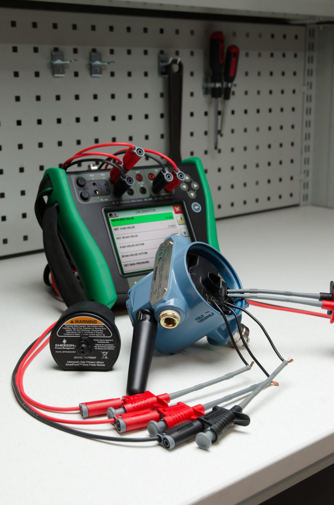
Fluke notes that a communicator on its own can read and change configuration but cannot measure or source an analog value. That is why every hart communicator calibration needs a reference such as a dead weight pressure tester or a multifunction process calibrator alongside the handheld.
Classic handheld with HART and Fieldbus support and a large device description library.
Newer touch screen communicator that Emerson says can also power a HART device on the bench.
Measures mA, sources and reads pressure with modules and talks HART in one box.
Hand pump with a reference gauge, pressure module or dead weight tester.
Fluke states that industry practice expects the measurement standard to be 4 to 10 times more accurate than the device under test. A 0.075 % transmitter therefore needs a pressure module, not a dial gauge.
How to Connect a HART Communicator With a 250 Ω Resistor
HART needs a minimum loop resistance of about 250 Ω so the digital current signal develops a readable voltage. Our article on the HART loop resistor shows why the handheld fails to find the device when this resistor is missing.
The resistor also eats supply voltage, because 20 mA through 250 Ω drops 5 V before the transmitter gets anything. A quick refresher on Ohm law and Kirchhoff voltage law helps you check that the transmitter still has its minimum lift off voltage at full scale.
On a bench with a 24 V supply, a 250 Ω resistor and a long cable, check the voltage at the transmitter terminals at 20 mA before you start. Use our HART loop voltage budget calculator if the margin looks tight.
Rerange vs Calibration: Is Rerange the Same as Calibration?
No, rerange only changes the LRV and URV numbers that define which pressures map to 4 and 20 mA, and it does not correct any sensor error. Calibration compares the transmitter against a reference and, if needed, trims the sensor or the output so readings match the standard.
- Changes LRV and URV in memory
- Needs no reference pressure when keyed in
- Like zero and span on an analog transmitter
- Does not fix sensor drift
- Compares output with a traceable standard
- Needs a known pressure and an accurate meter
- Sensor trim corrects the digital PV
- Output trim corrects the mA signal
Fluke explains that for a loop using only the 4 to 20 mA signal, rerange, analog output trim and zero trim are the relevant adjustments. If the host also reads the digital PV over HART, a sensor trim becomes necessary, which is also why the process variables in HART transmitters must be checked one by one.
HART Communicator Calibration Step by Step for a Pressure Transmitter
The sequence below follows the order used by Fluke and by Emerson in its Rosemount 3051 manual: test first, trim the sensor, trim the output, then verify. Doing hart communicator calibration in this order stops one correction from hiding another.
Record the as found readings before you touch anything, because they show how much the instrument drifted since the last visit. The format for those sheets is covered in our article on the calibration certificate with as found and as left data.
Emerson describes the analog output trim as a digital to analog trim, and its manuals ask for a precision ammeter in the loop.
Sensor Trim vs Output Trim: What Is the Difference?
Think of the sensor trim as fixing what the transmitter believes, and the output trim as fixing what it tells the DCS. A transmitter can need one, both or neither, which you only learn from a careful hart communicator calibration as found test.
| Point | Sensor Trim | Analog Output Trim |
|---|---|---|
| Converter adjusted | Analog to digital (input) | Digital to analog (output) |
| Reference needed | Known pressure source | Precision mA meter |
| Corrects | Digital PV reading | 4 and 20 mA loop current |
| Typical points | Lower and upper, or zero only | 4 mA then 20 mA |
| When to use | Digital PV used or sensor drift found | mA output off with correct PV |
Solved Example and mA Error Calculator
A 0 to 10 bar transmitter receives 5 bar from the reference, and the precision meter reads 12.05 mA. The tolerance is 0.5 % of span, so this hart communicator calibration point must stay inside that limit.
Expected = 4 + 16 × (5 ÷ 10)
Expected = 12.000 mA
Error = (12.05 minus 12.000) ÷ 16 × 100
Error = 0.31 % of span, PASS
Use the same calculator for every point of the five point test and write the error next to each reading. You can also check the result with the online calibration error tool or our calibration error calculation guide.
If errors grow steadily from 0 % to 100 %, the cause is usually span, while a constant error at every point points to zero. Our article on offset, zero and span error shows how to read these patterns quickly.
Loop Test With a HART Communicator
The loop test command forces the transmitter to output a fixed current, such as 4, 12 or 20 mA, without any pressure applied. Used at the end of hart communicator calibration, it proves the wiring, the DCS input card scaling and the alarms, as described in our pressure transmitter loop check procedure.
Fault currents below 3.6 mA and above 21 mA come from the NAMUR NE 43 recommendation, explained in our page on NAMUR NE 43. Always end the loop test from the handheld, or the transmitter may stay fixed at the forced current.
Common Errors in HART Communicator Calibration
Most failed calibrations come from a missing loop resistor, a poor reference, leaking test hoses or trimming in the wrong order. The table below lists each symptom with its likely cause and fix.
| Symptom | Likely Cause | Field Fix |
|---|---|---|
| No device found | Loop resistance below 250 Ω | Add resistor or connect across it |
| PV correct, mA wrong | Output stage drift | Run analog output trim |
| mA wrong at all points equally | Zero offset or mounting effect | Zero trim with ports vented |
| Error grows toward 20 mA | Span error | Full lower and upper sensor trim |
| Reading jumps or settles slowly | High damping or leak | Check damping value and test hose |
| Trim rejected by device | Trim points too close or wrong units | Use LRV and URV points in correct units |
Never trim a transmitter against the same meter you used to find the error unless that meter is traceable and better than the device. Our page on the calibration traceability chain explains why the reference must carry a valid certificate.
- Permit taken for hart communicator calibration and loop placed in manual
- Reference pressure standard within its calibration date
- At least 250 Ω in the loop for HART
- As found test recorded at five points
- Sensor trim done at LRV and URV points
- Output trim done at 4 and 20 mA
- As left test within tolerance and certificate saved
When a transmitter fails the as left test of a hart communicator calibration even after a full trim, move to fault finding instead of repeating trims. Our pressure transmitter troubleshooting guide covers impulse lines, diaphragm damage and electronics faults.
The Emerson reference manual below gives the official trim menus, trim point rules and loop test commands for a Rosemount transmitter.
The video below shows a Rosemount 3051 HART pressure transmitter being tested and trimmed with a Fluke 754 documenting calibrator.
HART Communicator Calibration FAQ
No, a handheld alone cannot calibrate a transmitter because it has no reference pressure and no accurate current meter. It can only rerange the device and run trim commands.
You also need a pressure reference about 4 times more accurate than the device and a precision milliammeter.
Sensor trim corrects the analog to digital stage so the digital pressure value matches a reference pressure. Output trim corrects the 4 to 20 mA loop current against a precision meter.
Do the sensor trim first, because the output depends on the digital value.
Find the expected current as 4 plus 16 times the applied pressure divided by span. Subtract it from the measured current, divide by 16 mA and multiply by 100.
For example, 5 bar on a 0 to 10 bar range expects 12.000 mA, so 12.05 mA is 0.31 % high.
About 250 ohms turns the small HART current changes into a readable voltage, and without it the handheld usually finds no device.
The resistor drops 5 volts at 20 mA, so a 24 volt supply leaves about 19 volts for the transmitter and cable.
The most common mistake is doing a rerange and calling it calibration, because rerange never compares the device with a standard. Another is trimming against an uncertified meter.
Always record as found readings first, use traceable references and repeat the five point test after every trim.
Many plants start with a 12 month interval and adjust it using as found history. Safety loops follow the proof test interval in the safety requirements specification.
If errors stay well within tolerance for three cycles, the interval can often grow to 24 months.
Related Articles
- Sensor Trim and Output Trim
- How the HART Protocol Works
- HART Loop Resistor in HART Communication
- Calibration Certificate As Found and As Left
- Pressure Transmitter Loop Check Procedure
External References
- Emerson: Rosemount 3051P Reference Manual
- Fluke: Calibrating a HART Smart Pressure Transmitter
- Wikipedia: Highway Addressable Remote Transducer Protocol
What We Learn Today
- HART communicator calibration needs a known pressure source and a precision meter, because the handheld alone can only configure and trim the transmitter.
- Sensor trim corrects the analog to digital stage while analog output trim corrects the 4 and 20 mA current that the DCS actually receives.
- Rerange changes only the LRV and URV values, so always record as found and as left readings at five points to prove real accuracy.