
A pressure switch that trips late or never resets can stop a pump, starve a burner or fail to protect a vessel. A careful calibration proves the exact trip point, reset point and deadband against a traceable reference.
Pressure switches look simple, yet a wrong setpoint or deadband can trip a plant or leave it unprotected. This guide walks through a practical, traceable calibration with a hand pump and a calibrator.

What Is Pressure Switch Calibration?
Pressure switch calibration is the process of applying a known, slowly changing pressure to a switch and recording the exact pressures at which its contact changes state on rising and on falling pressure. The results are compared with the required setpoint, reset point and tolerance, and the switch is adjusted if needed.
A pressure switch gives only an on or off output, so you cannot read its error from a display. You must watch the contact itself while pressure moves across the operating point.
The method differs from transmitter work because the output is a state, not a value. If you compare the two devices in pressure switch vs pressure transmitter, the need for a slow, careful ramp becomes clear.
Key Terms: Setpoint, Reset and Deadband
The setpoint, also called the trip or actuation point, is the pressure where the contact changes state. The reset point is where it returns to normal, and the gap between them is the deadband, explained in detail in deadband in pressure switches.
Beamex gives a simple example in which a switch closes at 10 psi and opens again at 9.5 psi, a deadband of 0.5 psi. The deadband stops the contact chattering when pressure hovers near the setpoint.
Changes state when rising pressure crosses the setpoint, resets on falling pressure.
Changes state when falling pressure crosses the setpoint, resets on rising pressure.
Acts on the difference between two pressures.
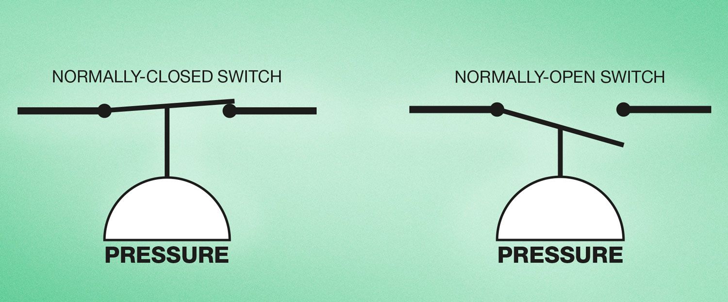
Contacts may be normally open or normally closed, and Beamex notes they can be dry contacts or wet contacts that switch a voltage. Always confirm which state is the normal state on the data sheet before the test.
Beamex advises that safety switches should not be exercised before the as found test. The very first operation shows how the switch would really behave in a demand after sitting idle for months.
Equipment Needed for Pressure Switch Calibration
- Pressure hand pump or comparator with a fine adjust vernier
- Reference gauge or calibrator with valid traceable certificate
- Multimeter or calibrator with a continuity function
- Test hoses, adapters and a vent or bleed valve
- Isolation permit and approved work procedure
- Calibration record sheet or documenting calibrator
- Tools for setpoint adjustment and sealing
A multifunction process calibrator can supply pressure readings and detect the contact at the same moment, which removes reading delay. For high accuracy work, a dead weight pressure tester gives the most stable reference pressure.
Choose a reference that is at least four times more accurate than the switch tolerance. The idea of measurement uncertainty in calibration explains why this ratio matters when results are close to the limit.
For pressure switch calibration, use a hand pump with a fine vernier so you can creep the pressure in tiny steps near the setpoint. A fast pump stroke always overshoots and makes the switch look late.
8 Steps of the Pressure Switch Calibration Procedure
Raise the pressure quickly up to about 90 percent of the expected trip, then move very slowly through the trip point. Beamex stresses that a slow ramp is the only way to capture the true operating point.
For a low setpoint switch, the order reverses, because the trip happens on falling pressure. Always test in the same direction the process will drive the switch.
Rising and Falling Tests in Practice
Fluke shows a worked case with a 12 psi high setpoint, a tolerance of plus or minus 1 psi and an allowed deadband of 1.5 to 2.5 psi. The switch is tested with a hand pump and the calibrator logs trip and reset by continuity.
In a good pressure switch calibration, run at least three cycles and record each trip and reset value. The spread between cycles is the repeatability, which is often as important as the absolute error.
Mechanical switches with a Bourdon or diaphragm element may drift with temperature, so test at a stable ambient. Let the reference settle for a few seconds at each reading.
In a Fluke documenting calibrator, an as found result outside tolerance is shown in reversed type. The technician then adjusts the switch and repeats the test as an as left run.
Pass or Fail Formula for Trip and Deadband
Two numbers decide the result of a pressure switch calibration: the trip error against the setpoint, and the deadband between trip and reset. Both must sit inside the limits on the data sheet or the plant calibration procedure.
Deadband = Measured trip minus Measured reset
Pass if |Trip error| ≤ Tolerance and Deadband is within its limits
Example, high setpoint switch:
Setpoint = 5.00 bar, tolerance = 0.10 bar
Trip = 5.04 bar, reset = 4.62 bar
Trip error = 5.04 minus 5.00 = 0.04 bar, PASS
Deadband = 5.04 minus 4.62 = 0.42 bar, within 0.30 to 0.50 bar, PASS
For a low setpoint switch, the deadband is the reset minus the trip, because the trip happens first on falling pressure. The calculator below uses the absolute difference, so it works for both cases.
Pressure Switch Calibration Calculator
Second Worked Example: Low Lube Oil Switch
A low lube oil pressure switch must trip at 1.50 bar falling with a tolerance of plus or minus 0.05 bar. The as found test gives a trip at 1.42 bar falling and a reset at 1.70 bar rising.
The trip error is 1.42 minus 1.50, which is minus 0.08 bar and outside tolerance, so the switch trips late on falling pressure. After adjustment, the as left trip is 1.49 bar and the reset is 1.68 bar, giving a 0.19 bar deadband.
In every pressure switch calibration, record both the as found and the as left values, since the as found result shows how long the switch was out of tolerance. That history feeds your calibration interval decisions.
Adjusting Setpoint and Deadband
Most switches have a range screw that moves the setpoint, and some have a second screw for the deadband. Adjust only after the as found pressure switch calibration test, as described in pressure switch setpoint and deadband configuration.
Turning the range spring changes both the trip and the reset together, while a deadband screw moves only one of them. Make small turns and repeat the full rising and falling test after each change.
Mark the starting position of the adjusting screw with a paint pen before you touch it. If the adjustment goes wrong, you can return to the original point quickly.
Common Pressure Switch Calibration Errors
| Problem | Likely Cause | Remedy |
|---|---|---|
| Readings change every cycle | Leak in hoses or fittings | Leak test the setup at full pressure |
| Trip always late | Ramp too fast near setpoint | Use vernier, slow the ramp |
| No contact change | Wrong terminals or broken microswitch | Check wiring and continuity first |
| Deadband too wide | Worn element or wrong adjuster | Readjust or replace the switch |
| Contact chatters | Vibration or very small deadband | Fit snubber, check mounting |
| Different results in field | Head of liquid in impulse line | Correct for elevation or calibrate in place |
If the switch sits below the tapping, a liquid filled line adds a static head that shifts the trip in service. The same correction logic appears in correction factor in calibration.
Before blaming the switch, check the wiring and the contact with a meter at the marshalling end. A healthy contact with a good insulation resistance rules out cable faults when nuisance trips occur.
Safety Switches, Records and Standards
Switches that act in an emergency shutdown system need extra care, with written bypass approval and a second person checking the restore. Their pressure switch calibration results are also part of the proof test record.
Calibration labs that certify reference gauges work to ISO 17025 laboratory requirements, which gives the traceability chain to national standards. In India, that chain usually leads back to the National Physical Laboratory.
A good record shows the tag, range, setpoint, tolerance, as found and as left trip and reset values, reference serial number and certificate date. Clear calibration terms on the form avoid confusion between trip, reset and deadband.
- Proves trips and alarms act at the right pressure.
- Finds drift before it causes a nuisance trip.
- Creates traceable records for audits.
- Builds trust in protective interlocks.
- Needs isolation and often a trip bypass.
- Slow ramps take time on many switches.
- Field conditions can differ from the bench.
- Results depend on reference quality.
Where Pressure Switches Are Calibrated Most
On panels where switches feed PLC alarms, confirm the first out alarm logic picks up the trip during the loop check after calibration. Compare the results with transmitter based trips as in how to calibrate a pressure sensor.
Fluke Application Note on Pressure Switch Testing
Pressure Switch Test Video
Pressure Switch Calibration FAQ
It is the test that finds the exact pressures where a switch trips and resets, using a traceable reference. The measured values are compared with the required setpoint, tolerance and deadband.
If the results are outside limits, the switch is adjusted and tested again. Both the as found and the as left values are written on the record sheet.
The setpoint is the pressure at which the contact changes state, also called the trip point. The reset is the pressure at which the contact returns to its normal state.
The gap between the two is the deadband of the switch. It prevents rapid chatter and repeated alarms when the process pressure hovers close to the setpoint.
The contact changes at one exact point, and a fast ramp carries the pressure past that point before you can read it. The switch then looks late on rising pressure and early on falling pressure.
Move quickly to about 90 percent of the setpoint and then creep forward slowly. A hand pump with a fine vernier makes this much easier.
A multimeter or calibrator is connected across the common and the normally open or normally closed terminals. It shows clearly and instantly when the contact closes or opens during the slow pressure ramp.
Many documenting calibrators record the pressure automatically at that exact instant. Always isolate the switch from live control circuits before connecting the meter.
Run at least three complete rising and falling cycles for a normal process switch on the bench or in the field. The spread between cycles shows the repeatability of the switch mechanism.
For safety switches, capture the very first operation as the as found result. Exercising them before the test can hide a sticky contact, a stiff diaphragm or a seized mechanism.
The tolerance comes from the data sheet, the safety requirements or the plant calibration procedure. In the Fluke example, a 12 psi setpoint has a tolerance of plus or minus 1 psi.
The deadband also has limits, such as 1.5 to 2.5 psi in that same example. Both the trip error and the deadband must pass for the switch to pass.
Many plants start with a yearly pressure switch calibration interval and then adjust it based on as found history. Switches that are often found out of tolerance need a shorter interval.
Safety switches follow the proof test interval set in the safety requirements. Record every result clearly so the chosen interval can be justified during audits.
Related Articles
- What Is a Pressure Switch
- Deadband in Pressure Switches
- Pressure Switch Setpoint and Deadband Configuration
- Multifunction Process Calibrator Uses
- Dead Weight Pressure Tester
External References
- Calibrating Pressure Switches with a DPC, Fluke Application Note
- Pressure Switch Calibration, Beamex Blog
- Pressure Switch, Wikipedia
What We Learn Today
- Pressure switch calibration records the exact trip and reset pressures on rising and falling ramps, then compares them with the setpoint, tolerance and deadband limits.
- A slow ramp near the setpoint, a continuity meter on the contact and a traceable reference are the three essentials for a correct and repeatable result.
- Always record as found values first, adjust only if needed, then repeat the test as left and seal the adjusting screw before restoring the loop.