A float switch is only a contact that opens or closes with level, but the way you wire it decides whether a tank fills, empties or overflows. Here is the wiring logic electricians and instrument engineers use every day.
Float switch wiring looks simple until a sump overflows because the wrong pair of wires was used. This guide explains the contact logic, wire colours, contactor and PLC circuits and the common faults.
What Is Float Switch Wiring?
Float switch wiring is the way the switch contacts are connected so that a rising or falling liquid level starts or stops a pump, opens a valve or raises an alarm. The two key choices are which contact you use, normally open or normally closed, and whether the float switches the load directly or drives a contactor, relay or PLC input.
- Pump down (empty a tank): contact closes when the float rises
- Pump up (fill a tank): contact closes when the float drops
- 3 wire floats have a common plus one wire for each action
- Switch large pumps through a contactor, never through the float alone
- Use two floats and a holding contact for a wide start and stop band
If you are new to the device itself, read our article on the float level switch working principle first. For choosing between floats and other point level devices, see level switch selection.
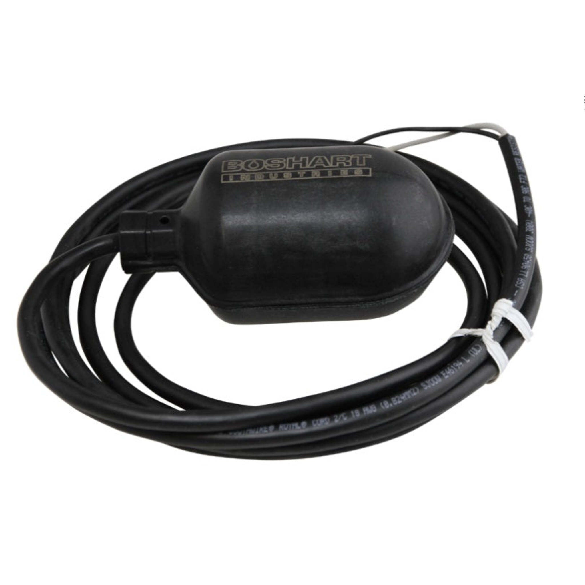
The photo shows a narrow angle control float with a three core cable, the most common type in float switch wiring. Cleanflow lists this type as 3 wire, 5 A at 120 or 240 V AC, usable for pump up with the normally closed pair or pump down with the normally open pair.
Normally Open vs Normally Closed Float Switch
NO and NC are always defined with the float hanging down at rest, which means low level. Sump Alarm explains that a normally open float carries no current while hanging and closes when water lifts it, while a normally closed float conducts while hanging and opens as the level rises.
| Contact | Float down (low level) | Float up (high level) | Typical use |
|---|---|---|---|
| Normally open (NO) | Open, pump off | Closed, pump on | Pump down, sump, drainage |
| Normally closed (NC) | Closed, pump on | Open, pump off | Pump up, filling, low alarm |
| Changeover (3 wire) | Common to down wire | Common to up wire | Either, by choosing the pair |
The same logic appears with pressure contacts, so our guide to pressure switch wiring NO and NC is a useful companion. Before any float switch wiring, confirm the state with a multimeter on continuity.
Float Switch Wiring Diagram for Pump Down and Pump Up
A 3 wire float has one common wire and two switched wires, so the float switch wiring decides the action. In the Sump Alarm series 2359 instructions, black is common, black plus brown gives normally empty for pump down, and black plus blue gives normally full for filling, with the unused wire capped.
| Application | Wires used | Contact closes when | Unused wire |
|---|---|---|---|
| Pump down (empty sump) | Black and brown | Float rises | Blue, capped and insulated |
| Pump up (fill tank) | Black and blue | Float drops | Brown, capped and insulated |
| High level alarm | Black and brown | Float rises | Blue, capped |
| Low level alarm | Black and blue | Float drops | Brown, capped |
Colours are not standard between makers. A German two contact float sold by Conrad uses blue for the mains supply, brown to the pump and green yellow for earth, and offers a red float to empty and a white float to fill.
Before mounting, hold the float vertical and then tilt it past horizontal while watching your meter. Mark the cable with tape as UP or DOWN so the next technician does not guess.
How to Wire a Float Switch to a Contactor
In industrial float switch wiring the float only switches the contactor coil, and the contactor switches the motor. The Sump Alarm instructions allow direct control only up to 1/2 HP (13 A) at 120 or 220 V AC, and say higher horsepower needs a contactor or relay.
Keep the motor thermal overload relay contact in series with the coil so that a tripped pump cannot restart on level alone. In a motor control centre, add an Auto Off Manual selector so the operator can bypass the float during maintenance.
Solved example, 0.75 kW, 230 V
PF 0.8, efficiency 0.8
FLC = 750 ÷ 147.2 = 5.1 A
Start at 6 × FLC = 31 A, more than 13 A
Result: use a contactor
The calculator compares the estimated starting current with the float rating, which is a cautious approach because motor inrush often welds small contacts. For 3 phase pumps always use a contactor, and size the feeder from the motor full load current.
Two Float Latch Circuit for a Pump
A single float starts and stops the pump within a few centimetres, which can cause short cycling. Two floats and a contactor holding contact give a wide band, because the pump starts at the high float and keeps running until the low float drops.
High float NO contact starts the pump, a contactor auxiliary NO in parallel holds it in, and the low float contact in series drops it out when the level falls.
Low float closes on low level to start the pump, the auxiliary contact holds, and the high float opens at full level to stop it.
A third float wired to a separate relay or PLC input gives a high high or low low alarm.
The holding contact works like a latch in logic, a topic explained in our article on latches in digital logic. Conrad gives a useful number for single floats too: with a 20 cm cable tether the switching points are about 36 cm apart.
Tether length sets the band of a cable float. The Sump Alarm instructions allow the tether to be cut as short as 3 inches from the float ribbing when only a wire tie is used, which gives a very narrow switching band.
How to Wire a Float Switch to a PLC
When a PLC controls the pump, float switch wiring treats the float as a dry contact on a 24 V DC digital input. Check whether the card is sinking or sourcing using our note on sinking and sourcing in PLC, then wire the float between the input and the correct supply rail.
- Start and stop delays prevent short cycling
- Pump alternation and run hour logging
- Alarms reach SCADA without extra relays
- Wire break can be detected with fail safe logic
- Float contacts must suit low current 24 V DC
- Contact bounce needs a small input filter
- Long cables near power lines pick up noise
- A failed PLC stops all level control
For high high alarms, use the contact that opens on alarm so that a cut cable also gives an alarm, which is the fail safe principle. A short input delay of about one second filters bounce, as explained in switch debouncing.
Float Switch Wiring Troubleshooting
Most float switch wiring faults are simple, but they hide inside a wet sump or a crowded panel. Use the table below before replacing the float.
| Symptom | Likely cause | Check |
|---|---|---|
| Pump never starts | Wrong pair used, cable cut, coil fuse blown | Continuity while lifting float |
| Pump never stops | Float stuck up, welded contact | Free movement, contact resistance |
| Rapid on off cycling | Tether too short, no latch circuit | Tether length, add second float |
| Pump runs backwards in logic | NO and NC pairs swapped | Swap to the other switched wire |
| Tripping earth leakage | Water in joint or cable damage | Insulation test, re seal joint |
| Random starts on PLC | Induced voltage on long cable | Shielded cable, input filter |
Run an insulation resistance test on float cables during shutdowns, because a damaged sheath lets water reach the contact. Disconnect any PLC card or electronic relay first so the test voltage cannot damage it.
For the test method and limits, see insulation resistance testing with a megger. If floats keep failing in dirty liquid, compare them with options in level switch vs level transmitter.
Float Switch Wiring Checklist
- Supply isolated and proven dead before work
- Common and switched wires identified with a meter
- Correct pair chosen for pump up or pump down
- Unused wire capped and sealed
- Contact rating checked against load current
- Overload contact in series with the coil
- Float tethered with free movement and no snagging
- Function tested by lifting and dropping the float
Before energising a new pump panel after float switch wiring work, walk through the electrical safety audit checklist. If you are replacing contactor control with interposing relays, read about solid state vs mechanical relays for the right choice.
In this R.C. Worst video a technician wires a float to a contactor for a pumping job. Pause it at the coil connection and compare it with the flow diagram above.
Float Switch Wiring FAQ
Good float switch wiring starts by finding the common wire, then checking which other wire closes on rising level and which on falling level. In the Sump Alarm design black is common, brown closes on rising level and blue closes on falling level.
Use the common and the brown wire to empty a tank, or the common and the blue wire to fill it. Cap and seal the unused wire.
It can be either, because the terms describe the contact with the float hanging down at low level. A normally open float closes when liquid lifts it, while a normally closed float opens as the level rises.
Many floats are changeover types with three wires, so one product does both jobs. Always check the state with a meter before you connect any supply.
Only small single phase pumps within the float contact rating can be switched directly. Sump Alarm allows direct control up to half a horsepower at 120 or 220 volts and asks for a contactor beyond that.
Motor starting current is several times the running current, which can weld small contacts. For 3 phase pumps and industrial duty, the float should only switch a contactor coil.
Wire the high float and a contactor auxiliary contact in parallel, then put the low float contact in series with that pair and the coil. The pump starts at high level, the auxiliary contact holds it in, and the low float drops it out.
This latch circuit gives a wide band between start and stop levels. It prevents short cycling and reduces wear on the pump and the contactor.
A pump down float empties a tank, so its contact closes when the level rises and opens when the level falls. A pump up float fills a tank, so its contact closes when the level drops and opens when the tank is full.
On a 3 wire float you choose the action by selecting the wire pair. The float body and cable stay exactly the same in both cases.
Common causes are the wrong wire pair, a stuck or snagged float, a blown control fuse or a tripped overload. Lift the float by hand and measure continuity across the wires you used.
If the contact changes but the pump stays off, check coil voltage at the contactor. If the contact never changes, the float or its cable is faulty and should be replaced.
Related Articles
- Float Level Switch Working Principle
- Pressure Switch Wiring NO and NC
- Sinking and Sourcing in PLC
- Thermal Overload Relay Explained
- Level Switch Selection Guide
External References
- Sump Alarm Series 2359 Float Switch Instructions (PDF)
- Sump Alarm: Normally Open vs Normally Closed Float Switches
- Float Switch, Wikipedia
What We Learn Today
- Float switch wiring starts with the contact state at low level, where a normally open float closes on rising level and a normally closed one on falling level.
- On a 3 wire float the chosen wire pair sets pump up or pump down action, and the unused wire must always be capped and sealed.
- Large pumps need a contactor, and a two float latch circuit with a holding contact gives a wide band that prevents short cycling.