
A simple DC test that reveals moisture, dirt and ageing in motor, cable and transformer insulation before it fails.
An insulation resistance test applies a high DC voltage between conductors and earth and measures the tiny leakage current that flows. The result, in megohms, shows whether insulation is clean, dry and healthy.
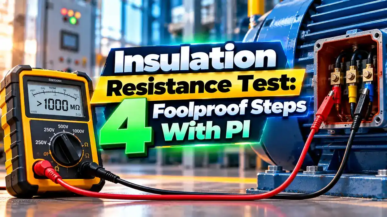
What Is an Insulation Resistance Test?
An insulation resistance test measures how well the electrical insulation of a motor, cable or transformer resists DC current. The instrument, often called a megger, applies 500 to 5000 V DC and displays resistance in megohms or gigohms.
Good insulation lets only a tiny current pass. Moisture, dirt, oil and cracks create leakage paths that lower the reading.

The total current has three parts, capacitive charging current, absorption current and leakage current. The first two fade with time, while leakage stays, which is why timed readings are so useful.
It is a key part of predictive and preventive maintenance for motors and cables. Trending readings over years often tells more than any single value.
4 Foolproof Steps to Perform the Test
Step 1 is a safety step, never skip it. Follow lockout tagout and your electrical isolation permit before touching any conductor.
Step 4 matters because long cables and large windings store charge like a capacitor. Discharge for at least as long as the test voltage was applied.
Choosing the Test Voltage
| Equipment AC Rating | Typical DC Test Voltage |
|---|---|
| Up to 100 V | 100 to 250 V |
| 440 to 550 V | 500 to 1000 V |
| 2400 V | 1000 to 2500 V |
| 4160 V and above | 1000 to 5000 V or higher |
These values come from the Megger insulation testing guide. Using too high a voltage on low voltage electronics can damage them, so disconnect drives and control cards first.
For a quick minimum check, Megger gives the old one megohm rule. Insulation should be about 1 MΩ per 1000 V of operating voltage, with a minimum of 1 MΩ.
PI, DAR and Temperature Correction Formula
DAR = R60 s ÷ R30 s
R40 = Rt × 0.5^((40 minus t) ÷ 10)
Rt = reading at winding temperature t in °C
Worked example at 30 °C:
R30 s = 600 MΩ, R1 min = 800 MΩ, R10 min = 2000 MΩ
DAR = 800 ÷ 600 = 1.33
PI = 2000 ÷ 800 = 2.5
R40 = 800 × 0.5^(10 ÷ 10) = 800 × 0.5
Corrected 1 minute reading = 400 MΩ at 40 °C
Resistance halves for about every 10 °C rise in temperature, so readings must be corrected before comparing. Always record winding temperature and humidity with each result.
PI is a ratio, so temperature affects it much less than single spot readings. That makes PI a more reliable health indicator for large motors.
How to Judge the Results
Excellent insulation condition.
Good condition, normal for most machines.
Questionable, often wet or dirty windings.
Poor insulation, do not energize.
Megger lists a DAR of 1.4 to 1.6 as good and above 1.6 as excellent. Values between 1.0 and 1.25 are questionable.
Motors@Work notes that PI above 5 can point to brittle epoxy, and PI loses meaning when the 1 minute reading exceeds about 5000 MΩ. Use judgement rather than a single number.
Types of Insulation Resistance Test
The spot reading is quick but sensitive to temperature. The time resistance method, which gives PI and DAR, is almost independent of temperature.
The step voltage test raises voltage in stages. A falling reading at higher voltage reveals cracks or contamination that low voltage tests miss.
Where the Insulation Resistance Test Is Used
For motors, the insulation class also sets the thermal limit. Our guide on motor insulation classes explains Class B, F and H ratings.
Transformer IR checks are part of routine tests and site acceptance. Record results with the date and temperature for future trending.
Weak insulation is not only a reliability problem but also a safety one. Leakage to a metal frame can create touch voltage, as explained in electrical shock causes and prevention, so good earthing and regular testing go together.
PI and Temperature Correction Calculator
A reading taken at a temperature above 40 °C will be corrected upward. This is expected because hot insulation shows lower resistance.
- Detects moisture and dirt early.
- Simple, portable and non destructive.
- PI is almost independent of temperature.
- Trends predict failures before they happen.
- Always isolate and discharge first.
- Disconnect electronics before testing.
- Correct readings for temperature.
- Never compare values taken at different voltages.
Megger Guide to Insulation Testing PDF
Megger PI Test Video
Insulation Resistance Test FAQ
Related Articles
- Motor Insulation Classes
- What Is Electrical Insulation
- Lockout Tagout Explained
- Electrical Safety PPE Selection
- Predictive vs Preventive Maintenance
External References
- A Stitch in Time Insulation Testing Guide, Megger
- Megger Q and A on IR Testing
- Insulation Resistance Indices, Motors@Work
- Megohmmeter, Wikipedia
What We Learn Today
- A megger applies high DC voltage and measures insulation resistance in megohms.
- PI and DAR ratios reveal moisture and dirt better than a single reading.
- Correct readings to one base temperature and always discharge after testing.