
A current transformer only tells the truth when the load on its secondary stays within the VA it was designed for. Add up the relay, the meter and the long copper leads correctly and your protection trips and energy bills stay trustworthy.
Every relay, meter and metre of cable on a current transformer secondary adds load that the core must drive. A careful CT burden calculation keeps accuracy within class and stops the core from saturating during a fault.
What Is CT Burden?
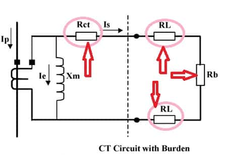
CT burden is the total load connected across the secondary terminals of a current transformer, expressed in volt amperes at rated secondary current or in ohms. It includes the relay or meter input, the lead wires going to the panel and back, and every terminal and test block in the loop, as explained in our guide on the current transformer working principle.
A current transformer behaves like a current source, so a larger secondary impedance forces it to develop a higher voltage to push the same current. By Ohm law, that voltage is simply secondary current times loop impedance, and the core flux has to rise to produce it.
Accuenergy defines CT burden as the maximum load that can be applied to the secondary of a current transformer. It notes that the value is stated either as total impedance in ohms or as total VA and power factor at a specified current and frequency.
Why the VA Rating Matters in Real Panels
If the connected load is higher than the rated value, the core works at higher flux and the ratio and phase errors grow. For a metering core this means wrong kWh bills, and for a protection core it means early saturation during a fault.
If the secondary is ever opened while primary current flows, the burden becomes practically infinite and the voltage can reach dangerous levels. That hazard is covered in detail in CT secondary open circuit risks, and it is the extreme case of the same physics.
For the same cable, a 5 A secondary produces 25 times more lead loss than a 1 A secondary, because loss rises with the square of current. This single fact is why long outdoor runs in Indian substations almost always use 1 A CTs.
Components of Total CT Burden
The VA or ohm value of each device input, taken from its datasheet at rated current.
The copper wire from the CT terminals to the panel and back, calculated as I² times loop resistance.
Test terminal blocks, shorting links and lugs, usually a small allowance of a few milliohms each.
Modern numerical relays usually present a small input burden, while older electromechanical units need several VA. When you compare relay families in protective relays explained, always note the input burden per phase alongside the setting range.
The lead loop is a plain resistance problem, so the resistance formula R = ρ × L ÷ A applies directly. Copper resistivity rises with temperature, so a hot cable trench or a summer rooftop in Rajasthan adds real error.
Always read the relay burden at the rated secondary current of your CT, not at the relay setting. If a datasheet gives the input in ohms, convert it to VA with the square of your rated secondary current.
CT Burden Calculation Formula
The standard approach adds every VA in the secondary loop and compares the total CT burden with the rated output of the core. For the leads, the loop resistance uses conductivity of copper, commonly taken as 57 m per Ω mm² at room temperature.
Lead burden: VA lead = In² × R loop
Total CT burden = VA relay + VA meter + VA lead
L = one way length in m, A = cable size in mm², In = rated secondary current
Example:
In = 5 A, relay = 1 VA, L = 50 m, A = 2.5 mm²
R loop = 2 × 50 ÷ (57 × 2.5) = 100 ÷ 142.5 = 0.702 Ω
VA lead = 5² × 0.702 = 17.54 VA
Total = 1 + 17.54 = 18.54 VA, choose 20 VA
The factor of 2 covers the go and return conductors, which is the conservative case for single phase to earth faults. In this example the leads consume almost 95 percent of the total, so a 15 VA core would be overloaded even though the relay itself needs only 1 VA.
CT Burden Calculator
Second Worked Example With a 1 A Secondary
Keep the same 50 m route and 2.5 mm² cable, but change the secondary to 1 A and use a relay input of 0.5 VA. The loop resistance stays 0.702 Ω, but the lead burden falls to 1² × 0.702 = 0.70 VA.
The total CT burden becomes only 1.20 VA, so a 2.5 VA or 5 VA core is enough with a healthy margin. This is why utilities and large plants in India specify 1 A secondaries for outdoor switchyards where the control building is far away.
- Lead burden 25 times lower for the same cable.
- Smaller CT core and lower cost for the same accuracy.
- Long cable runs possible with 2.5 mm² wire.
- Lower open circuit voltage stress on leads.
- Some older meters and relays accept only 5 A.
- Higher turns count on the secondary winding.
- Spare parts must match the panel standard.
- Testing kits must be set for the lower current.
6 Proven Steps to Size CT Burden
Step six links the secondary load to the fault level, so you need the maximum through fault from your short circuit fault current calculation. Without that number, the accuracy limit check is only a guess.
Keep the connected load for a metering core at or above 25 percent of rated VA. IEC 61869 part 2 defines ratio error limits across that range, and a very lightly loaded core can drift outside its declared class.
Accuracy Class and CT Burden Together
| Class | Used For | Error Limit | Typical Rated VA |
|---|---|---|---|
| 0.2S and 0.5S | Revenue and tariff metering | Tight limits down to 1 percent current | 5 to 10 VA |
| 0.5 and 1 | Panel meters and energy monitoring | 0.5 or 1 percent ratio error at rated current | 5 to 15 VA |
| 5P10 and 5P20 | Overcurrent and earth fault relays | 5 percent composite error up to ALF | 10 to 30 VA |
| 10P10 and 10P20 | General feeder protection | 10 percent composite error up to ALF | 10 to 30 VA |
| PX or PXR | Differential and distance protection | Defined by knee point voltage and Rct | Not stated in VA |
In 5P20, the 5 means a composite error of 5 percent and the 20 is the accuracy limit factor, so the core stays accurate up to 20 times rated current at rated burden. In India these classes follow IS 16227 part 2, which is aligned with IEC 61869 part 2.
Metering cores carry an instrument security factor such as FS5, so they saturate early and protect the meter during faults. For tariff work, even a small ratio error distorts every energy consumption calculation over a year.
A protection core loaded well below its rated VA actually reaches a higher real accuracy limit factor. The same effect on a metering core is unwelcome, because it lets fault current pass into the meter before saturation.
Actual ALF and Knee Point Check
ABB, in its application note on the accuracy limit factor, gives the relation Fa = Fn × (Sin + Sn) ÷ (Sin + Sa). Here Sin is internal burden, Sn is rated burden and Sa is actual connected burden, all in VA.
Example: 5P20, 15 VA, Rct = 0.2 Ω, In = 5 A
Sin = 5² × 0.2 = 5 VA
Sa = 18.54 VA from the first example
Fa = 20 × (5 + 15) ÷ (5 + 18.54) = 16.99
So the 15 VA core, overloaded by excess CT burden, accurately reproduces only about 17 times rated current instead of 20 times. ABB also shows an internal resistance of 0.07 Ω giving an internal burden of 1.75 VA at 5 A, which you add in exactly the same way.
For PX class cores used in transformer differential protection, the rule is expressed as a voltage. The knee point must exceed K × If × (Rct + R loop + R relay), where the factor K comes from the relay maker.
Choosing Between 1 A and 5 A Secondary
Choose 5 A where the relay and meters sit in the same panel as the CT, such as an LT switchboard with short internal wiring. Choose 1 A when the cable run exceeds a few tens of metres or goes to a remote control room.
Motor feeders in large plants often use 1 A cores for the numerical relays described in motor protection relay types. Overcurrent settings still follow the plug setting and time multiplier logic in IDMT relay characteristics.
In a VCB or SF6 panel, the CT chamber often holds separate metering and protection cores on one primary. Each core has its own CT burden limit, so calculate each loop separately.
Common Mistakes in CT Burden Sizing
- Using one way length instead of the go and return loop.
- Forgetting test terminal blocks, links and auxiliary CTs.
- Taking relay VA at 1 A and applying it to a 5 A core.
- Specifying 30 VA for a metering core with only 3 VA connected.
- Checking ALF against rated instead of actual CT burden.
- Mixing metering and protection cores during site changes.
Accuracy Limit Factor Application Note
Video on CT Burden and Cables
CT Burden FAQ
It is the total load connected to the secondary of a current transformer, including relays, meters and cables. It is stated in volt amperes at rated secondary current or in ohms.
A higher load forces the core to work at higher flux. Accuracy then falls, and a protection core may saturate before the fault current reaches its limit.
Multiply the loop impedance by the square of the rated secondary current. Accuenergy shows a 600/5 A example where 4.16 ohms gives 25 times 4.16, or 104 volt amperes.
The same impedance on a 1 A secondary gives only 4.16 volt amperes. That is why the rated current must always be stated along with any CT burden value.
Lead loss rises with the square of current and in direct proportion to cable length. On a 5 A circuit, a 50 m run of 2.5 square millimetre copper adds about 17.5 volt amperes.
On a 1 A circuit the same cable adds only about 0.7 volt amperes. Short runs, thicker cable or a 1 A secondary keep the lead share of the load within limits.
The 5 is the composite error limit of 5 percent, and the letter P stands for protection. The 20 is the accuracy limit factor when rated load is connected.
So the core keeps its accuracy up to 20 times rated current at rated CT burden. With more connected load than rated, the real limit falls below 20 and the relay may see a distorted current.
For protection cores, extra VA gives margin but increases core size, weight and cost. For metering cores, a very lightly loaded core may drift away from its declared accuracy class.
A practical target keeps the actual connected load between 25 and 100 percent of the rating. Size the core to the real calculation, not to a large round number picked for comfort.
Disconnect the CT, inject rated secondary current into the loop from the terminals, and measure the voltage across it. Voltage multiplied by current gives the real volt amperes of the loop.
Compare the result with the design sheet and the nameplate rating before commissioning. Also confirm a single earthing point and tight terminals, since loose links raise the loop resistance.
Use 1 A when cables are long, such as outdoor switchyards and remote control rooms. It cuts lead loss by 25 times for the same cable and keeps the core small.
Use 5 A when all devices sit close to the CT inside one switchboard. Many older meters also accept only 5 A inputs, so check device compatibility before you finalise the rating.
Related Articles
- Current Transformer Working Principle
- CT Secondary Open Circuit Risks
- Protective Relays Explained
- Transformer Differential Protection 87T
- IDMT Relay Characteristics TMS and PSM
External References
- Calculation of the Current Transformer Accuracy Limit Factor, ABB
- CT Burden Reference, Accuenergy
- Current Transformer, Wikipedia
What We Learn Today
- CT burden is the total VA of relays, meters, terminals and the lead loop, where lead burden equals the square of secondary current times loop resistance.
- A 5 A secondary makes 25 times more lead loss than a 1 A secondary, so long outdoor cable runs in Indian substations usually use 1 A cores.
- Actual accuracy limit factor falls when connected load exceeds rated load, so always verify 5P20 or PX cores using the real calculated loop value.