
By comparing current entering and leaving a transformer, the relay trips fast for internal faults and stays stable for everything outside.
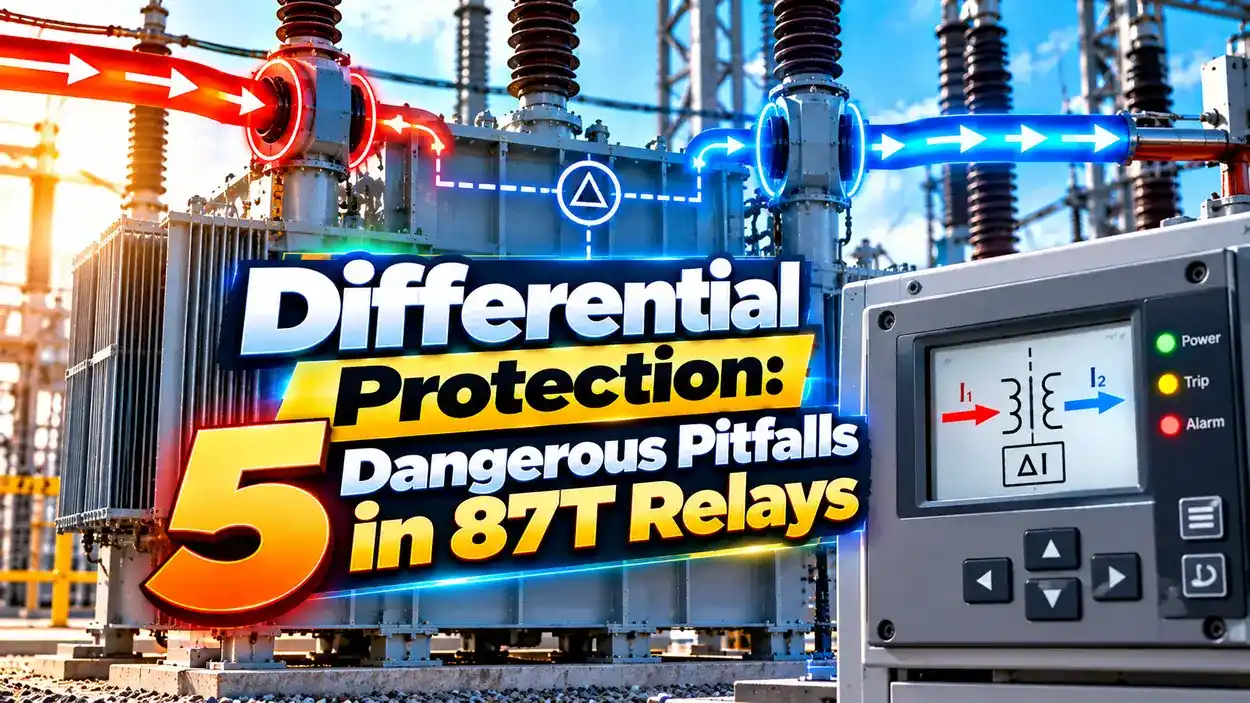
Differential protection compares the current entering a protected zone with the current leaving it. If the difference is large, the fault must be inside the zone, so the relay trips instantly.
What Is Differential Protection?
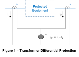
Differential protection is a unit protection scheme that measures the current at both ends of a protected zone and trips when they do not balance. It applies Kirchhoff current law directly, since current entering a healthy zone must equal current leaving it.
The zone is defined by the location of the current transformers on each side. Anything between the CTs is protected, and anything outside is ignored.
Because the scheme does not need to coordinate with downstream devices, it can trip very fast. That speed limits damage to expensive transformer windings.
PAC Basics notes that transformer differential relays are generally applied on units of 10 MVA and above, and sometimes on 5 MVA units. The ANSI device number is 87T.
How the Biased Differential Relay Works
The relay calculates an operate current from the difference and a restraint, or bias, current from the average of the two sides. Tripping needs the operate current to exceed both a minimum pickup and a slope times the bias.
The slope allows for errors that grow with current, such as CT mismatch and tap changer movement. At high through fault currents, a second, steeper slope adds security against CT saturation.
Typical minimum pickup is 0.2 to 0.3 times the relay tap. This covers normal magnetizing current of about 1 to 4 percent.
Differential Protection Formula With Worked Examples
Ibias = (I in + I out) ÷ 2
Trip when Id > Pickup and Id > Slope × Ibias
Settings: Pickup = 0.3 pu, Slope = 25 percent
External fault with CT error:
I in = 10 pu, I out = 9.2 pu
Id = 0.8 pu, Ibias = 9.6 pu, limit = 2.4 pu
Result: no trip, stable
Internal fault fed from one side:
I in = 10 pu, I out = 0 pu
Id = 10 pu, Ibias = 5 pu, limit = 1.25 pu
Result: trip
The example shows why a plain overcurrent relay could not tell these two faults apart. The bias makes the relay less sensitive only when high current flows straight through the transformer.
PAC Basics lists tap variation near 10 percent, CT error of 3 to 10 percent and relay error near 5 percent. Together these explain why slopes of 25 to 30 percent are common.
5 Dangerous Differential Protection Pitfalls
Pitfall 2 is where many commissioning errors start. Our guide on transformer vector groups explains how Dyn11 and similar groups shift phase.
Pitfall 1 connects with CT selection and wiring. Never leave a live CT secondary open, as warned in CT secondary open circuit risks.
Inrush and Overexcitation Restraint
When a transformer is energized, the core can saturate and draw a large inrush current on one side only. The relay sees it as a differential current, so it must recognize the second harmonic content and hold off.
An SEL technical paper notes that inrush second harmonic used to be expected near 16 to 17 percent, but modern cores can show much less than 10 percent. Typical settings sit around 10 to 15 percent.
Overexcitation produces strong fifth harmonic. The same paper suggests fifth harmonic restraint around 35 percent to stay secure for overvoltage below about 140 percent.
An unrestrained high set element trips instantly for very large internal faults. It ignores harmonics because such currents cannot be inrush.
Types of Differential Protection
Biased scheme with ratio, vector and harmonic compensation.
Compares neutral and terminal currents of the stator.
Protects large motor windings from internal faults.
Sums all feeders connected to a busbar.
Compares currents at both line ends over communication.
Sensitive earth fault scheme for one winding.
All of these share the same principle as other protective relays, but each adds its own compensation. Busbar schemes, for instance, must handle many CTs with very different loading.
Restricted earth fault protection is often added to transformer differential protection. It detects earth faults near the star point that the main scheme may miss.
Differential vs Overcurrent Protection
| Feature | Differential | Overcurrent |
|---|---|---|
| Zone | Clearly bounded by CTs | Not bounded |
| Speed | Instantaneous | Time delayed |
| Coordination needed | No | Yes |
| Sensitivity to internal faults | High | Lower |
| Backup for other zones | No | Yes |
| Cost | Higher | Lower |
Differential relays protect only their own zone, so overcurrent protection is still needed as backup. Our article on breaker coordination explains how backup timing is set.
Many modern numerical relays combine both functions in one box. They also record disturbances for later analysis.
Bias Characteristic Calculator
Enter 0 for the current out to simulate an internal fault fed from one side. The result will change to trip.
- Very fast tripping for internal faults.
- No coordination with other relays.
- Stable for through faults with bias.
- Clear, well defined protection zone.
- Wrong CT ratio or vector compensation.
- False trips on inrush without restraint.
- CT saturation on heavy through faults.
- Provides no backup outside its zone.
Harmonic Restraint Technical Paper
Biased Differential Settings Video
Differential Protection FAQ
Related Articles
- Protective Relays Explained
- Current Transformer Working Principle
- Transformer Vector Group Explained
- Motor Protection Relay Types
- Short Circuit Current Calculation
External References
- Biased Differential Protection for Transformers, PAC Basics
- Harmonic Blocking and Restraint, SEL
- Transformer Differential Protection ANSI 87T, Smartelec
- Differential Protection, Wikipedia
What We Learn Today
- The relay trips when current in and out of its zone do not balance.
- Bias slopes and harmonic restraint keep it stable for through faults and inrush.
- Correct CT ratio and vector group compensation are essential before energizing.