
Too many cables in one pipe overheat, scrape their insulation during the pull and leave no room for future circuits. A quick area check, a jam ratio test and a look at pulling tension keep every run safe and easy to install.
Conduit fill is the share of a raceway cross section taken up by the cables inside it. Keeping it within the 53, 31 and 40 percent limits makes pulling easier, cooler and safer.

What Is Conduit Fill?
Conduit fill is the percentage of the inside cross sectional area of a conduit that is occupied by the cables or conductors pulled into it. It is the first check an electrical designer makes after selecting cable size for the load current, because the cable outside diameter decides how big the pipe must be.
Too little free space, or excessive conduit fill, causes three problems: the pull needs more force, the insulation is scraped at bends and the cables run hotter. Heat matters because grouped cables already need cable derating factors applied to their current rating.
Fill Limits of 53, 31 and 40 Percent
The best known conduit fill rule comes from NEC Chapter 9, Table 1, which most Indian consultants also quote in project specifications. It allows 53 percent of the conduit area for one cable, 31 percent for two cables and 40 percent for more than two cables.
A short conduit nipple of 600 mm or less between enclosures may be filled to 60 percent, since such a short piece is easy to pull and has little length to trap heat. Every other run follows the 53, 31 and 40 percent rule.
The 40 percent conduit fill limit does not mean 60 percent of the pipe is wasted. Round cables leave gaps between them anyway, so 40 percent of area already looks crowded when you view the pipe end on.
Conduit Fill Formula Step by Step
The conduit fill formula works on areas, not diameters. You add the cross sectional area of every cable, using its overall outside diameter from the datasheet, and divide by the inside area of the conduit.
Conduit fill percent = Sum of cable areas ÷ (π × D² ÷ 4) × 100
For equal cables: Fill percent = n × d² ÷ D² × 100
Jam ratio = D ÷ d
n = number of cables, d = cable outside diameter, D = conduit inside diameter
Example: 4 cables of 8 mm OD in a conduit of 28 mm ID
Fill = 4 × 8² ÷ 28² × 100 = 256 ÷ 784 × 100
Fill = 32.65 percent, below the 40 percent limit, PASS
Jam ratio = 28 ÷ 8 = 3.50
Use the inside diameter of the conduit, not the nominal size. The nominal size printed on Indian PVC or steel conduit is not its bore, so take the inside diameter from the maker catalogue, just as you would take busbar dimensions in busbar sizing.
VIOX Electric shows a classic case of nine 12 AWG THHN conductors in a 3/4 inch EMT. Each conductor has an area of 0.0133 square inch, the total is 0.1197 square inch and the EMT area is 0.533 square inch, which gives 22.5 percent and passes the area check.
Conduit Fill Calculator
6 Proven Steps to Size a Conduit
Step one is where most errors start, because people use the conductor size in square millimetres instead of the overall cable diameter. Armoured cables in particular are much fatter than the copper inside them, as you will notice when choosing cable glands for the same cable.
Jam Ratio: The Hidden Pulling Problem
Jamming happens when three cables lie side by side in a bend and wedge across the pipe. EC and M explains that the jam ratio is the conduit inside diameter divided by the cable outside diameter, and that a ratio of 2.8 to 3.2 means jamming may be an issue.
| Jam ratio D ÷ d | Jamming probability (Cerrowire) |
|---|---|
| Below 2.3 | Very small |
| 2.3 to 2.6 | Small |
| 2.6 to 2.8 | Moderate |
| 2.8 to 3.0 | Significant |
| 3.0 to 3.1 | Moderate |
| 3.1 to 3.2 | Small |
| 3.2 and above | Very small |
The Cerrowire installation guide also adds a 5 percent allowance because a conduit bend becomes slightly oval. In its own example, EC and M finds that a 2 inch rigid conduit with an inside diameter of 2.083 inch and 4/0 AWG XHHW 2 cable of 0.653 inch gives 3.19, so jamming may be an issue.
Moving to a 3 inch conduit raises the ratio to 4.73 and removes the risk. A jam ratio problem can therefore exist even when the conduit fill looks perfectly acceptable.
Measure the real cable diameter with a vernier before a three cable pull in a tight conduit. Cerrowire warns that published diameters vary, and a 0.5 mm difference can move you into the jamming band.
Second Worked Example: Three Power Cables
Suppose three single core cables of 12 mm overall diameter must run in a conduit with a 35 mm bore. The fill is 3 × 144 ÷ 1225 × 100 = 35.27 percent, which passes the 40 percent limit.
The jam ratio is 35 ÷ 12 = 2.92, which falls in the significant band of the Cerrowire table. Choosing a conduit with a 40 mm bore gives a jam ratio of 3.33 and a fill of 3 × 144 ÷ 1600 × 100 = 27.0 percent, so both checks pass.
Pulling Tension and Sidewall Pressure Basics
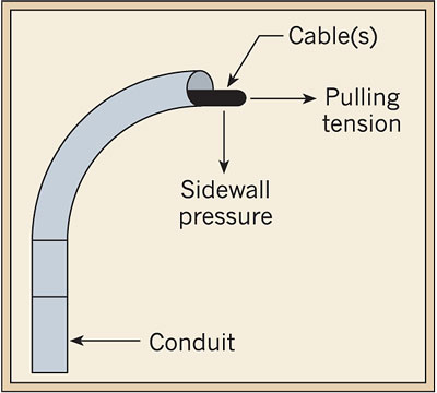
Cerrowire gives the maximum pulling tension on copper conductors with a pulling eye as T = 0.008 × n × CMA in pounds, where CMA is the circular mil area of each conductor. It also asks you to reduce that value by 20 percent when more than three conductors are pulled together.
Straight section: Ts = L × W × f
Bend: Tc = T1 × e^(f × a)
Example: three 4/0 AWG copper conductors, CMA = 211,600
T = 0.008 × 3 × 211,600 = 5,078 lb
L = length, W = cable weight per length, f = friction coefficient, a = bend angle in radians
Bends multiply tension rather than add to it, so a short run with many 90 degree bends can still exceed the cable limit, whatever its conduit fill. EC and M notes that the coefficient of friction is about 0.1 to 1.0 with pulling compound and may exceed 1.0 in a dry conduit.
Sidewall pressure is the crushing force of the cable against the inside of a bend. Cerrowire allows 1,000 lb per foot for 600 V and 1 kV non shielded power cable, and too much pressure shows up later as low readings in an insulation resistance test.
Static friction is higher than sliding friction, so a stopped pull needs more force to restart. EC and M therefore advises that a cable pull should not be stopped once it has begun.
Conduit Fill Practice in India
In India, conduits for electrical installations are covered by IS 9537, with separate parts for rigid steel and rigid PVC types, while wiring practice follows IS 732. Our overview of electrical regulations and standards explains how these codes fit with CEA safety regulations.
Many Indian EPC specifications simply adopt the 40 percent conduit fill limit and add a minimum conduit size for field wiring. Always check the project specification first, because a client rule can be stricter than the general practice.
For long trunk routes, cable tray or ladder is often cheaper than many parallel conduits, and its loading follows cable tray fill calculation rules instead. Heavy bus runs inside buildings may suit a bus duct system better than cables in pipe.
Heavy galvanised steel pipe with threaded joints, good mechanical protection.
Light, non corroding and easy to bend with heat or bends.
Spiral metal or plastic hose for the last connection to equipment.
In classified areas, conduit sealing and gland practice matter as much as fill, as covered in hazardous area classification. Flexible conduit at motor terminals also needs its own earth continuity, so follow earth conductor sizing for the bonding jumper.
Benefits and Limits of Fill Rules
- Easier, faster pulls with less force.
- Less insulation damage at bends.
- Better heat dissipation in service.
- Spare room for future circuits.
- Area check alone does not catch jamming.
- Ignores pulling length and number of bends.
- Does not replace ampacity derating.
- Catalogue diameters may differ from real cables.
Conduit fill only answers whether the cables fit and can be pulled safely. Current rating, voltage drop and short circuit withstand are separate checks that must also pass for every feeder.
Conduit Fill Inspection Checklist
- Overall cable diameters taken from datasheets or measured on site.
- Correct limit used for one, two or more cables.
- Conduit inside diameter taken from the maker catalogue.
- Jam ratio checked for every three cable run.
- Number of bends between pull points kept low.
- Pulling compound and a tension meter planned for long pulls.
- Insulation resistance tested after pulling.
Keep pull boxes at reasonable spacing on long runs with several bends. Splitting one difficult pull into two easy ones protects the cable far better than extra force.
Where Fill Calculations Matter Most
For motor circuits, combine the conduit check with cable sizing for motor feeders so that the cable and pipe are chosen together. Instrument signal pairs often need shielded twisted pair cable, which is fatter than plain wire of the same size.
Cerrowire Installation Guide PDF
Conduit Fill Video Example
Conduit Fill FAQ
It is the percentage of the inside area of a conduit occupied by the cables pulled into it. The value comes from the total cable area divided by the conduit inside area.
Keeping it low makes pulling easier and reduces heat build up. It also leaves space for any future circuits that may be added later.
Round cables cannot pack a round pipe tightly, so free space is needed for them to slide and bend. The 40 percent figure gives that clearance while still using the pipe well.
One cable may use 53 percent because it cannot wedge against another. Two cables get only 31 percent because they can jam across the pipe at bends.
Always use the overall outside diameter of the finished cable, including insulation, sheath and any armour. The conductor size in square millimetres says nothing about how fat the finished cable really is.
Take the value from the cable datasheet or measure a sample with a vernier on site. Real cables can be slightly larger than the catalogue figure.
Jam ratio is the conduit inside diameter divided by the cable outside diameter. It matters mainly when exactly three cables are pulled together through bends.
A ratio between 2.8 and 3.2 means the three cables may wedge side by side in a bend. Choosing a larger or smaller conduit moves the ratio safely out of that band.
Yes, because the area check ignores jamming, bends and pulling length. A long run with several bends may need more force than the cable can safely take.
Check the jam ratio, the pulling tension and the sidewall pressure as well for every difficult run. Adding a pull box in the middle often solves the problem at little cost.
IS 9537 covers conduits for electrical installations, with parts for rigid steel and rigid PVC types. Wiring practice for buildings follows the code of practice given in IS 732.
Many project specifications in India adopt the 40 percent fill limit from the American electrical code. Always read the client specification first, since it may set stricter rules for each run.
Work out π × d² ÷ 4 for each cable using its own outside diameter. Add all the areas together to get the total cable area for the run.
Divide that total by the conduit inside area and multiply by 100 to get the percentage. Compare the result with the 40 percent limit when there are three or more cables.
Related Articles
- Cable Tray Fill Calculation
- Cable Derating Factors
- Cable Sizing and Ampacity Explained
- Voltage Drop Calculation
- Cable Sizing for Motor Feeders
External References
- Cerrowire Installation Information, Cerrowire
- The Basics of Cable Pulling, EC and M
- Electrical Conduit, Wikipedia
What We Learn Today
- Conduit fill is the share of conduit area used by cables, limited to 53 percent for one cable, 31 percent for two and 40 percent for more.
- Cable area is π × d² ÷ 4 using the overall outside diameter, so four 8 mm cables in a 28 mm bore give 32.65 percent fill.
- For three cables, avoid a jam ratio of 2.8 to 3.2, and keep pulling tension and sidewall pressure within cable maker limits.