
Cable Sizing and Ampacity Calculation Explained: Derating Factors and Formula
A cable rated 100A on the datasheet almost never actually carries 100A safely once it's bundled with other cables, sitting in a hot panel, or buried in warm soil. Derating is the honest math that closes that gap.
Cable sizing determines the minimum conductor size that safely carries a load's current without overheating, while also keeping voltage drop within limits. This guide explains ampacity, the key derating factors, the sizing procedure, and a live ampacity derating calculator.
What is Ampacity?
Ampacity is the maximum current a conductor can carry continuously without exceeding its insulation's rated temperature. Manufacturer catalog ampacity values are quoted under fixed reference conditions, typically 30°C ambient air with a single, unbundled cable. Real installations almost never match these conditions exactly, which is why derating factors exist: they adjust the catalog ampacity down to reflect the actual, hotter, more crowded conditions a cable will really operate in.
Proper cable sizing must satisfy two separate checks: the derated ampacity must exceed the design load current, and the resulting voltage drop over the actual cable run must stay within acceptable limits, commonly 3% for branch circuits and 5% total from source to load. Whichever check demands the larger conductor determines the final cable size.
Real Life Example
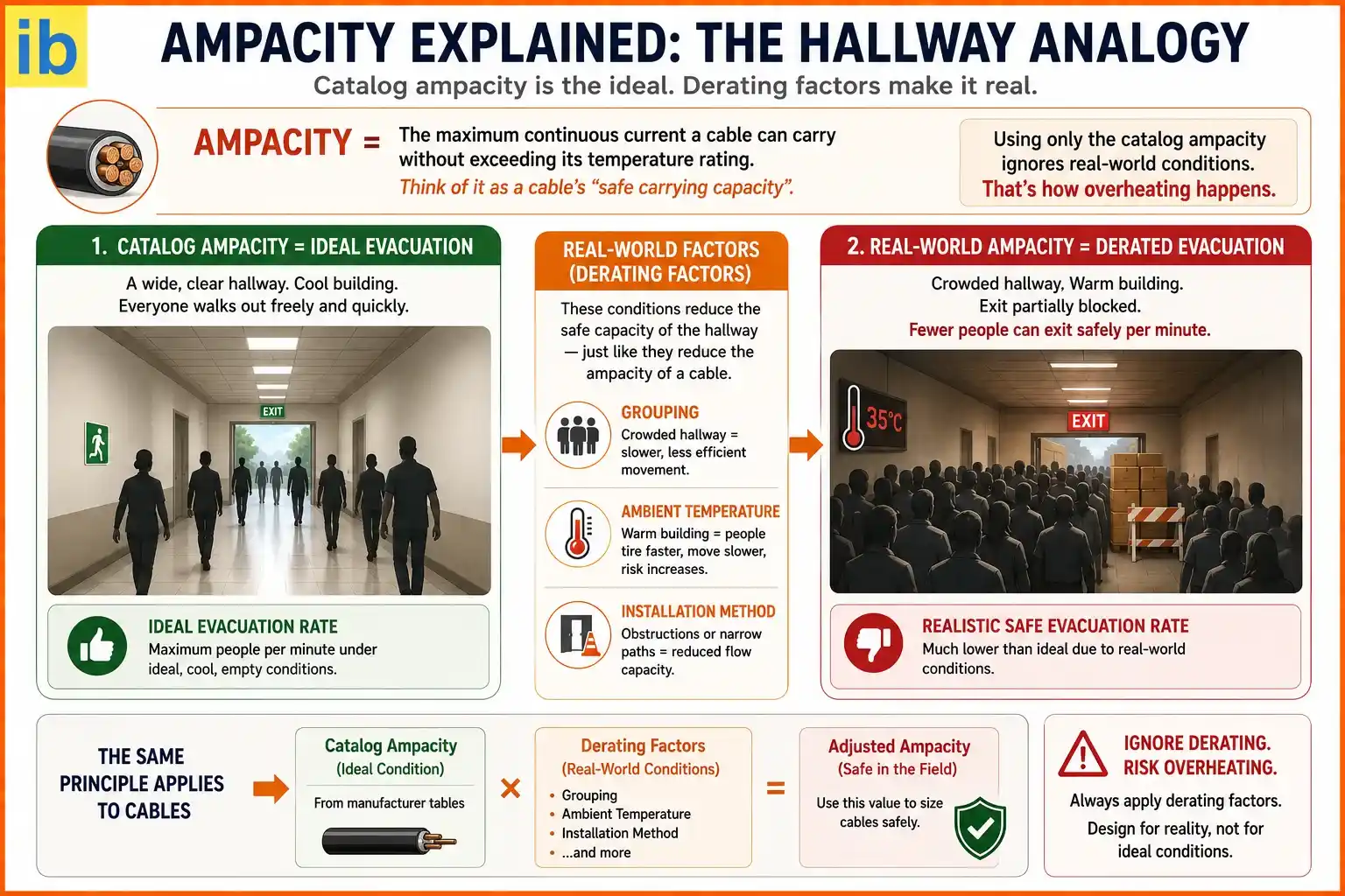
Think of ampacity like the maximum number of people a hallway can safely evacuate through per minute under ideal, cool, empty conditions. Now imagine that same hallway crowded with other people (grouping), the building already warm from a fire (ambient temperature), and the exit partially obstructed (installation method). The realistic safe evacuation rate drops well below the ideal number, and pretending otherwise, using only the catalog figure, is exactly the kind of mistake that causes cables to overheat in the field.
Cable Sizing Procedure
Calculate Design Current
Determine the actual load current (Ib) from the connected equipment's power, voltage, and power factor.
Select Protective Device
Choose an overcurrent device rating (In) at or above the design current.
Apply Derating Factors
Multiply catalog ampacity by temperature, grouping, and installation method factors.
Check Voltage Drop
Verify the run length doesn't push voltage drop beyond the allowed limit, upsizing if needed.
Derating Formula
The golden rule is that the protective device must protect the cable, not just the connected appliance. Design current must be no greater than the protective device rating, which in turn must be no greater than the cable's derated ampacity: Ib ≤ In ≤ Iz.
Ampacity Derating Calculator
Cable Ampacity Derating Calculator
Based on Iz = Ib x Ct x Cg x CiCommon Derating Factors
| Factor | Effect |
|---|---|
| Ambient Temperature | Higher ambient reduces ampacity; ratings are typically referenced to 30°C air or 20°C soil |
| Grouping | Multiple cables bundled together reduce each cable's ability to shed heat |
| Installation Method | Buried, enclosed conduit, or restricted airflow all reduce ampacity vs open free air |
| Soil Thermal Resistivity | Dry, sandy soil resists heat transfer more than wet, compact soil for buried cables |
| Depth of Burial | Deeper burial reduces a buried cable's ability to dissipate heat |
| Harmonic Currents | Non-linear loads like VFDs can add triplen harmonics that increase neutral conductor heating |
Applications
Motor Feeder Cables
Ampacity and voltage drop both matter for reliable motor starting and running performance.
Building Distribution
Panel and feeder cables are sized against grouped, enclosed conduit conditions.
Underground Cable Runs
Soil thermal resistivity and burial depth significantly affect buried cable ampacity.
Solar Installations
Rooftop cable runs face severe derating from high ambient heat and UV exposure.
VFD and Drive Circuits
Harmonic-aware sizing prevents neutral conductor overheating in nonlinear loads.
Long Feeder Runs
Voltage drop, not just ampacity, often governs cable size over long cable lengths.
Cable Derating: Video Walkthrough
Frequently Asked Questions
- Electrical Engineering Planet, Derating Factors of Cables: How to Calculate Safe Ampacity
- Enginist, Cable Sizing Guide: IEC Standards and Calculations
- MEPBase, Cable Size Calculation: Formula and Example
What We Learn Today
- Ampacity is a cable's maximum safe continuous current, quoted under fixed reference conditions
- Real installations require derating for ambient temperature, grouping, and installation method
- Derated ampacity follows Iz = Ib x Ct x Cg x Ci, and design current must satisfy Ib ≤ In ≤ Iz
- Both ampacity and voltage drop must independently pass; the larger resulting cable size wins
- Grouping is often the single most significant derating factor in real-world installations