
Selecting a cable for a motor feeder is not simply picking a size that matches the motor nameplate current.
Two derating factors (ambient temperature and cable grouping) can reduce current carrying capacity by 30 to 40%, forcing a larger cable size than nameplate current alone suggests.
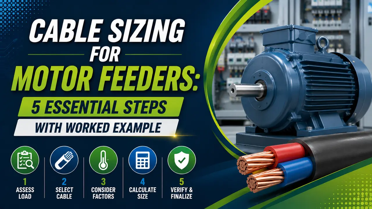
This guide covers the five step IEC method with a full worked example for a 22 kW motor feeder and an interactive calculator.
A cable that is correctly sized for current carrying capacity can still fail the voltage drop check on a long run. Both criteria must be satisfied independently -- the larger of the two results is the final cable size.
Why Motor Feeders Need Special Attention
A motor draws more current than its full load rating under certain conditions. At startup, inrush can reach 6 to 7 times the full load value, though this lasts only seconds.
The cable does not carry startup current continuously, but the overcurrent protection device must tolerate it.
IEC 60364-4-43 requires the design current to be at least 1.25 times the motor full load current (FLC).
This 25% margin covers service factor and thermal reserve. See the MCB sizing guide for overcurrent device selection.
The 5-Step Cable Sizing Procedure
Use the three phase motor current formula: FLC = P / (√3 × V × pf × η). P is motor output power in watts, V is line voltage, pf is power factor, and η (eta) is efficiency. All values are from the motor nameplate.
Design current I_design = 1.25 × FLC. This is the minimum current the cable must carry continuously. The cable's derated ampacity must exceed this value.
Find the ambient temperature correction factor Ca from IEC 60364-5-52 Table B.52.14, and the grouping factor Cg from Table B.52.17. Combined derating = Ca × Cg. If no other derating applies, use 1.0 for that factor.
Required minimum ampacity: Iz_min = I_design / (Ca × Cg). Pick the smallest standard cable from the IEC 60364 table whose rated ampacity Iz_table equals or exceeds Iz_min. Verify: Iz_table × Ca × Cg ≥ I_design.
Apply the three phase voltage drop formula using the FLC (not design current): V_drop = 1.732 × FLC × L × R / 1000.
Percentage drop must be within 5%. See the voltage drop calculation guide for the full procedure.
Derating Factor Reference
These are the most commonly used derating factors from IEC 60364-5-52 for PVC insulated copper cables. XLPE cables have different correction factors -- always check the manufacturer's datasheet for the specific insulation type.
IEC 60364 Ampacity Table: Copper PVC in Conduit (30°C, Single Circuit)
| Cable Size (mm²) | Ampacity Iz at 30°C (A) | Resistance at 70°C (Ω/km) | Typical Motor Rating at 415V |
|---|---|---|---|
| 1.5 | 15 | 15.00 | Up to 0.55 kW |
| 2.5 | 20 | 9.18 | Up to 0.75 kW |
| 4 | 25 | 5.72 | Up to 1.5 kW |
| 6 | 32 | 3.82 | Up to 2.2 kW |
| 10 | 44 | 2.27 | Up to 4 kW |
| 16 | 57 | 1.43 | Up to 7.5 kW |
| 25 | 73 | 0.780 | Up to 15 kW |
| 35 | 90 | 0.554 | Up to 22 kW |
| 50 | 108 | 0.420 | Up to 30 kW |
| 70 | 136 | 0.332 | Up to 45 kW |
| 95 | 164 | 0.247 | Up to 55 kW |
| 120 | 188 | 0.196 | Up to 75 kW |
Worked Example: 22 kW Motor Feeder, 120 m Run
A 22 kW, 415V, three phase induction motor has a power factor of 0.85 and efficiency of 0.92. The feeder runs 120 m from the MCC. Site ambient temperature is 45°C. Three motor feeder cables are routed together in the same conduit.
FLC = 22,000 / (1.732 × 415 × 0.85 × 0.92) = 39.1 A
FLC = 22,000 / (1.732 × 415 × 0.85 × 0.92) = 39.1 AI_design = 1.25 × 39.1 = 48.9 ACa = 0.79 (45°C, PVC), Cg = 0.70 (3 circuits), Combined = 0.79 × 0.70 = 0.553Iz_min = 48.9 / 0.553 = 88.4 A73 × 0.553 = 40.4 A < 48.9 A90 × 0.553 = 49.8 A > 48.9 AV_drop = 1.732 × 39.1 × 120 × 0.554 / 1000 = 4.51 V = 1.09%Motor Cable Sizing Calculator
Cable Sizing for Motor Feeders -- Common Questions
External References
- IEC 60364-5-52 -- Wiring Systems: Selection and Erection of Electrical Equipment
- Motor Selection and Application Guide -- ABB
What We Learn Today
- Design current for motor circuits = 1.25 × FLC (IEC 60364-4-43 requirement)
- Combined derating = Ca × Cg -- can reduce effective capacity to below 55% in hot, grouped installations
- Required ampacity = I_design / (Ca × Cg) -- select the next standard cable above this value
- Voltage drop uses FLC, not design current -- V_drop = 1.732 × FLC × L × R / 1000
- Both ampacity and voltage drop must pass -- take the larger cable if they give different answers
- VFD output cables need an extra derating allowance for harmonic heating