
One winding, one core and a tap in the middle can do the job of a full transformer with far less copper. The price is that input and output are connected, so knowing where the trick works and where it is unsafe matters.
An autotransformer uses one winding for both primary and secondary, so part of the power passes straight through by conduction. That makes it smaller, cheaper and more efficient, but it gives no electrical isolation.

What Is an Autotransformer?
An autotransformer is a transformer with a single winding on one core, where a portion of that winding is common to both the input and the output circuits. It works on the same induction principle as any transformer, explained in Faraday law of electromagnetic induction, but it saves material because primary and secondary share turns.
In a step down autotransformer the supply is connected across the whole winding and the load is taken from a tap and one end. In a step up unit the supply goes to the tap and the load takes the full winding.
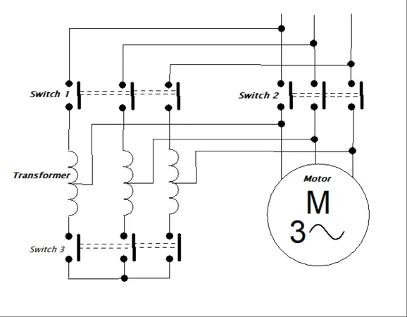
The voltage ratio still follows the turns ratio, just as in transformer turns ratio and secondary voltage. What changes is how the power travels from input to output.
How an Autotransformer Transfers Power
In a two winding transformer, every watt reaches the load through the magnetic core. In an autotransformer, part of the power flows straight from supply to load through the shared copper, and only the rest is transformed magnetically.
Conducted power = S × K
Transformed power = S × (1 minus K)
Common winding current = I low minus I high
Example: 230 V to 180 V, load S = 2 kVA
K = 180 ÷ 230 = 0.783
I high = 2000 ÷ 230 = 8.70 A, I low = 2000 ÷ 180 = 11.11 A
Common winding current = 11.11 minus 8.70 = 2.42 A
Transformed power = 2 × (1 minus 0.783) = 0.43 kVA
This example shows the real advantage. Only 0.43 kVA of the 2 kVA load passes through the core, and the common section of the autotransformer carries just 2.42 A instead of 11.11 A, so it can be wound with much thinner wire.
The core and series section are sized for the transformed power, which is why an autotransformer is so compact when the two voltages are close. Rating rules for normal units are covered in transformer kVA rating calculation.
When the voltage ratio is close to 1, almost all the power is conducted and very little is transformed. A 230 V to 220 V autotransformer handles about 96 percent of its load by direct conduction.
Copper Saving in an Autotransformer
For the same rating and voltage ratio, the copper needed by an autotransformer is (1 minus K) times the copper of a two winding transformer. The saving is therefore K times the copper of the two winding design.
Copper saving = K × Copper in two winding
K = 0.783: copper needed = 21.7 percent, saving = 78.3 percent
K = 0.5: copper needed = 50 percent, saving = 50 percent
K = 0.1: copper needed = 90 percent, saving = 10 percent
The table makes the rule clear: the closer the two voltages, the bigger the saving. For a ratio like 11 kV to 433 V, K is tiny, the saving disappears and an autotransformer would be both pointless and dangerous.
Autotransformer Calculator
Autotransformer vs Two Winding Transformer
| Feature | Autotransformer | Two winding transformer |
|---|---|---|
| Windings | One, with a tap | Separate primary and secondary |
| Electrical isolation | None | Yes |
| Copper for same rating | 1 minus K times | Full amount |
| Size, losses and cost | Lower when K is near 1 | Higher |
| Impedance and fault level | Lower impedance, higher fault current | Higher impedance |
| Best ratio range | Close voltages | Any ratio |
The lower leakage impedance gives better regulation but lets more fault current through, so check the downstream breaker duty with a short circuit current calculation. Smaller copper and core also mean lower losses, a point you can test with transformer efficiency calculation.
Core losses still follow the usual split described in eddy current loss and hysteresis loss. An autotransformer simply needs less core for the same throughput power.
6 Essential Autotransformer Uses
The common thread in all six uses is a modest voltage change where isolation is not required. Wherever the ratio is large or user safety needs separation, an isolating transformer is chosen instead.
Autotransformer Starter for Induction Motors
An autotransformer starter feeds the motor through taps at reduced voltage, then switches it to full line voltage. EEPower describes taps generally set between 50 and 80 percent of line voltage, and notes that the starting current drawn from the supply falls with the square of the voltage ratio.
| Tap | Motor voltage | Line current, percent of DOL | Starting torque, percent of DOL |
|---|---|---|---|
| 80 % | 80 % | 64 % | 64 % |
| 65 % | 65 % | 42 % | 42 % |
| 50 % | 50 % | 25 % | 25 % |
The Sprecher and Schuh reduced voltage starter catalogue lists exactly these figures for its autotransformer starters. Line current falls with the square because the motor current falls with voltage and the autotransformer itself steps that current down again.
Compared with star delta, the autotransformer starter offers a choice of taps and gives more torque per ampere of line current. The wider comparison is covered in motor starting methods compared and DOL vs star delta starter.
This five step sequence is the closed transition, or Korndorfer, method. Sprecher and Schuh lists its autotransformer starters as closed transition, which avoids the current and torque surge of an open changeover.
Start with the 65 percent tap and move to 80 percent only if the motor stalls or the run up takes too long. Every step up in tap raises the line current and the voltage dip on the bus.
Second Worked Example: Tap Selection
A pump motor with 100 A full load current draws about 600 A when started direct on line. On the 65 percent tap the motor current becomes 0.65 × 600 = 390 A, and the line current becomes 0.65 × 390 = 253.5 A, about 42 percent of the direct online value.
The starting torque falls to the same 42 percent, so check that this exceeds the load torque at all speeds. Use motor full load current data and the motor starting voltage dip calculation to confirm the bus voltage stays acceptable.
Schneider Electric lists a duty of fifteen 15 second starts per hour for NEMA sizes 2 to 5 in its reduced voltage starter catalogue. Frequent starting heats the autotransformer, so it is not meant for jogging duty.
Variac: The Variable Autotransformer
A variac is a toroidal autotransformer with a carbon brush that slides over bare turns on the winding. Moving the brush changes the tap point smoothly, so the output can be set anywhere from zero to slightly above the input voltage.
Laboratories and repair benches use it to bring up old equipment slowly, test relays at reduced voltage or check how a product behaves at low mains. Remember that a variac is still an autotransformer, so its output is never isolated from the mains.
Always connect the variac neutral terminal to the supply neutral, never to the phase. A reversed connection leaves the output terminals at line potential even when the dial reads zero.
Grid Interconnecting Autotransformer
In Indian transmission substations, the interconnecting transformer that links the 400 kV and 220 kV systems is normally a three phase autotransformer bank. The ratio is close to 2, so a large share of power is conducted and the unit is much smaller than a two winding design, a benefit that helps in GIS and AIS substations alike.
Such units usually carry a delta tertiary winding to provide a path for third harmonic currents and stabilise the neutral. They also carry an on load tap changer for voltage control, and their connection follows the rules in transformer vector groups.
Supply across full winding, load across part of it.
Supply across part of winding, load across full winding.
Sliding brush gives a continuous tap.
No Isolation: The Main Safety Risk
Because the output is part of the input winding, a fault that opens the common section puts nearly the full input voltage on the load. A step down autotransformer from 415 V can therefore expose low voltage equipment to the full supply.
The lack of separation also carries any earth fault or neutral shift straight through, so the earthing scheme must suit the TN, TT and IT earthing systems on both sides. Where people touch the output, choose real galvanic isolation instead.
- Less copper and core for the same rating.
- Higher efficiency and lower losses.
- Better voltage regulation.
- Smaller size and lower cost.
- No electrical isolation between circuits.
- Higher fault current from low impedance.
- Savings vanish at large voltage ratios.
- Open common winding exposes load to full voltage.
Autotransformer Inspection Checklist
- Confirm the voltage ratio suits an autotransformer, ideally below about 2 to 1.
- Check fault level and breaker rating on the output side.
- Verify neutral and earth connections on both circuits.
- Inspect variac brush and track for wear and arcing.
- Check starter tap setting and timer against the motor run up time.
- Record insulation resistance and winding resistance during maintenance.
Large grid units also go through the full set of transformer routine and type tests before energisation. Winding resistance on each tap and ratio tests confirm that the common and series sections are correct.
Reduced Voltage Starter Catalogue PDF
Autotransformer Power and Control Video
Autotransformer FAQ
It is a transformer with one winding on one core, where part of the winding is common to both circuits. The output is taken from a tap on that single winding.
Part of the power flows straight through the shared copper and only the rest is transformed magnetically. This makes the unit smaller and cheaper than a two winding design.
The copper needed is (1 minus K) times that of a two winding transformer, where K is the low to high voltage ratio. The saving is therefore K times the two winding copper.
For 230 V to 180 V, K is 0.783 and the saving is about 78 percent. For a ratio of 10 to 1 the saving is only about 10 percent.
The input and output circuits share the same winding, so they are electrically connected. Any fault or high voltage on the input side can reach the connected load directly.
If the common section of the winding opens, the load can see almost the full input voltage. Use an isolating transformer wherever people or sensitive circuits need separation.
Typical taps are 50, 65 and 80 percent of line voltage. Sprecher and Schuh lists line current and torque of 25, 42 and 64 percent of direct online values.
The line current falls with the square of the tap ratio. Starting torque falls in the same proportion, so pick the lowest tap that still accelerates the load.
A variac is a variable autotransformer built on a toroidal core with a sliding carbon brush. Moving the brush changes the output voltage smoothly from zero upward.
It is widely used on test benches and in laboratories. Its output is not isolated from the mains, so handle it with the same care as live wiring.
The 400 kV to 220 kV ratio is close to 2, so a large share of power can be conducted directly. The unit becomes smaller, lighter and more efficient than a two winding design.
Both networks are solidly earthed systems, so the lack of isolation is acceptable there. A delta tertiary winding is usually added to handle third harmonic currents.
Avoid it when the voltage ratio is large, because the copper saving almost disappears. Avoid it too wherever user safety depends on proper isolation from the supply.
Examples include control circuits handled by operators, medical equipment and portable tool supplies on construction sites. In those places a proper double wound isolating transformer is the correct choice.
Related Articles
- Transformer Turns Ratio and Secondary Voltage
- Motor Starting Methods Compared
- On Load Tap Changer OLTC
- Transformer Efficiency Calculation
- What Is Galvanic Isolation
External References
- Reduced Voltage Starters Catalogue, Sprecher and Schuh
- Motor Starters Part 10: Autotransformers, EEPower
- Autotransformer, Wikipedia
What We Learn Today
- An autotransformer uses one tapped winding for both circuits, so part of the power is conducted directly and only the rest is transformed magnetically.
- Copper needed is (1 minus K) times a two winding unit, so a 230 V to 180 V design saves about 78 percent copper.
- Starter taps of 50, 65 and 80 percent give line current and torque of 25, 42 and 64 percent, but there is never isolation.