
A tiny coil current can switch a heavy load, but the voltage kick when that coil turns off can destroy the transistor driving it.
A relay uses a magnetic field to move a set of contacts, giving full isolation between a low power control circuit and a high power load. It remains one of the most used components in panels and circuit boards.
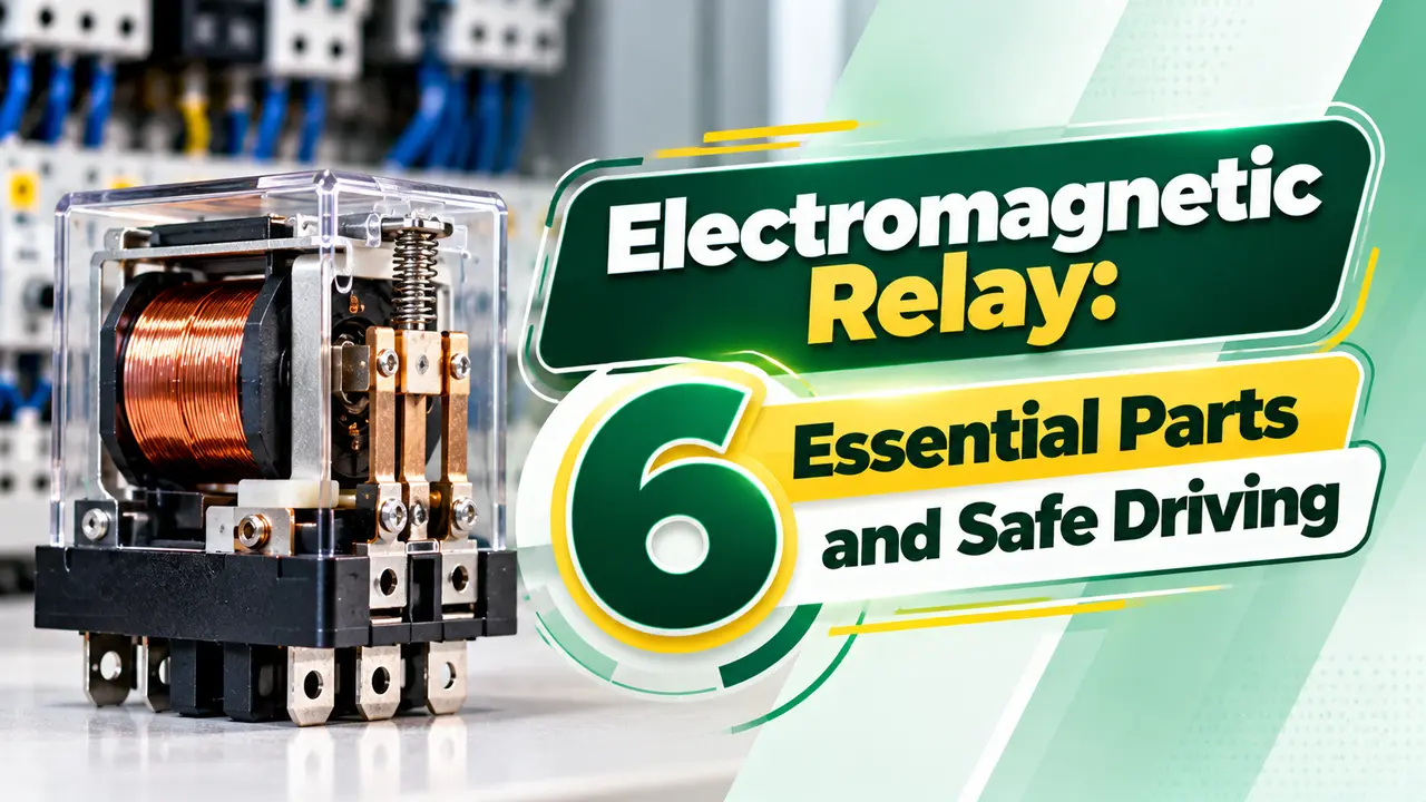
What Is an Electromagnetic Relay?
An electromagnetic relay is a switch operated by an electromagnet, where current through a coil pulls an iron armature that opens or closes mechanical contacts. The coil circuit and contact circuit are electrically isolated, which is the main difference from a transistor switch.
An electromagnetic relay switches AC or DC, handles surges well and show almost zero resistance when closed. Their weaknesses are speed, contact wear and the inductive kick from the coil.
In control panels, relays multiply outputs, interface voltages and isolate field signals from PLC digital outputs. Safety versions with forced guided contacts are covered in safety relays.
On circuit boards, a small signal electromagnetic relay switches audio, test lines and mains loads from a microcontroller. The same physics applies at every size.
6 Essential Parts
Contacts are made from silver alloys chosen for the load type. Gold plated contacts suit very low currents where oxide films would block conduction.
Contact forms are named by poles and throws, such as SPST, SPDT and DPDT. A DPDT unit switches two separate circuits with one coil.
How the Electromagnetic Relay Operates
Pickup and dropout voltages are different, giving built in hysteresis. This stops chatter when the supply wanders a little.
Coil inductance means current rises and falls with a time constant, just like any inductor. Operate and release times are typically a few milliseconds.
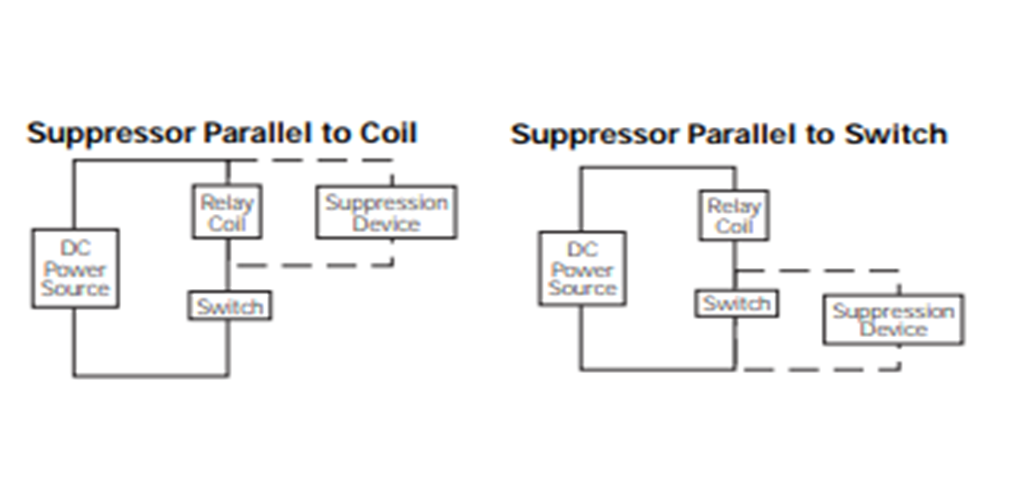
Coil Suppression: Diode vs TVS
TE Connectivity reports that a 12 V DC coil can produce a 1000 to 1500 V spike when it is switched off. Without suppression, that spike can break down the transistor driving the electromagnetic relay.
A flyback diode across the coil clamps the spike to about one diode drop above the supply, as AutomationDirect explains. Choose it from the diode types available, usually a 1N4007 or a fast switching diode.
| Method | Spike Clamp | Release Speed | Notes |
|---|---|---|---|
| Plain diode | About 1 V above supply | Slowest | Can reduce contact life |
| Diode plus zener | Zener voltage | Fast | Good balance |
| TVS diode | TVS clamp voltage | Fast | TE preferred method |
| RC snubber | Moderate | Medium | Works on AC coils |
TE explains that a plain diode slows the armature and can lead to contact welding. A TVS diode or a diode with a zener lets the field collapse faster.
Driving the Coil From a Microcontroller
Base current Ib = Ic ÷ 10, forced gain for saturation
Rb = (V in minus 0.7) ÷ Ib
Worked example:
12 V coil, 400 Ω, Ic = 30 mA, coil power 0.36 W
5 V logic, Ib = 3 mA
Rb = 4.3 ÷ 0.003 = 1433 Ω
Use a 1.2 kΩ base resistor and a flyback diode
An NPN transistor sinks the coil current to ground, the same idea as sinking and sourcing outputs. A microcontroller pin alone cannot supply 30 mA safely.
ULN2003 driver ICs combine seven transistors with built in diodes, which makes them popular for relay boards with four, eight or sixteen channels.
Coil Driver Calculator
Pick the next lower standard resistor to ensure full saturation. Check that the transistor collector rating exceeds the coil current with margin.
- Full isolation between circuits.
- Switches AC or DC.
- Very low on resistance.
- Handles surge currents.
- Slow compared with transistors.
- Contacts wear and arc.
- Coil needs suppression.
- Audible click and vibration sensitivity.
For silent, fast or very frequent switching, compare the options in solid state vs mechanical relay.
Transient Suppression PDF
Relay Working Animation
Electromagnetic Relay FAQ
Related Articles
- Solid State vs Mechanical Relay
- What Is a Safety Relay
- TVS Diode Explained
- Basics of Transistors
- Thermal Overload Relay
External References
- Transient Suppression for Inductive Loads, AutomationDirect
- Relay Coil Suppression, TE Connectivity
- Relay, Wikipedia
What We Learn Today
- An electromagnetic relay uses a coil and armature to switch heavy loads with isolation.
- Suppress the coil spike, preferably with a TVS or diode plus zener.
- Drive the coil with a saturated transistor or a driver IC.