
The cell constant (K) of a conductivity sensor defines the electrode geometry and converts raw conductance to specific conductivity in mS/cm.
Choosing the wrong cell constant causes inaccurate readings, even with a correctly functioning analyser.
This guide covers what cell constant means, how to select the right value for your process, and how to calibrate it using standard KCl solution.
Cell constant K = L/A (electrode gap over electrode area). A larger K suits high conductivity solutions. A smaller K gives better resolution in very low conductivity water. Units are cm⁻¹.
The Cell Constant: What It Is and Why It Matters in Conductivity Measurement
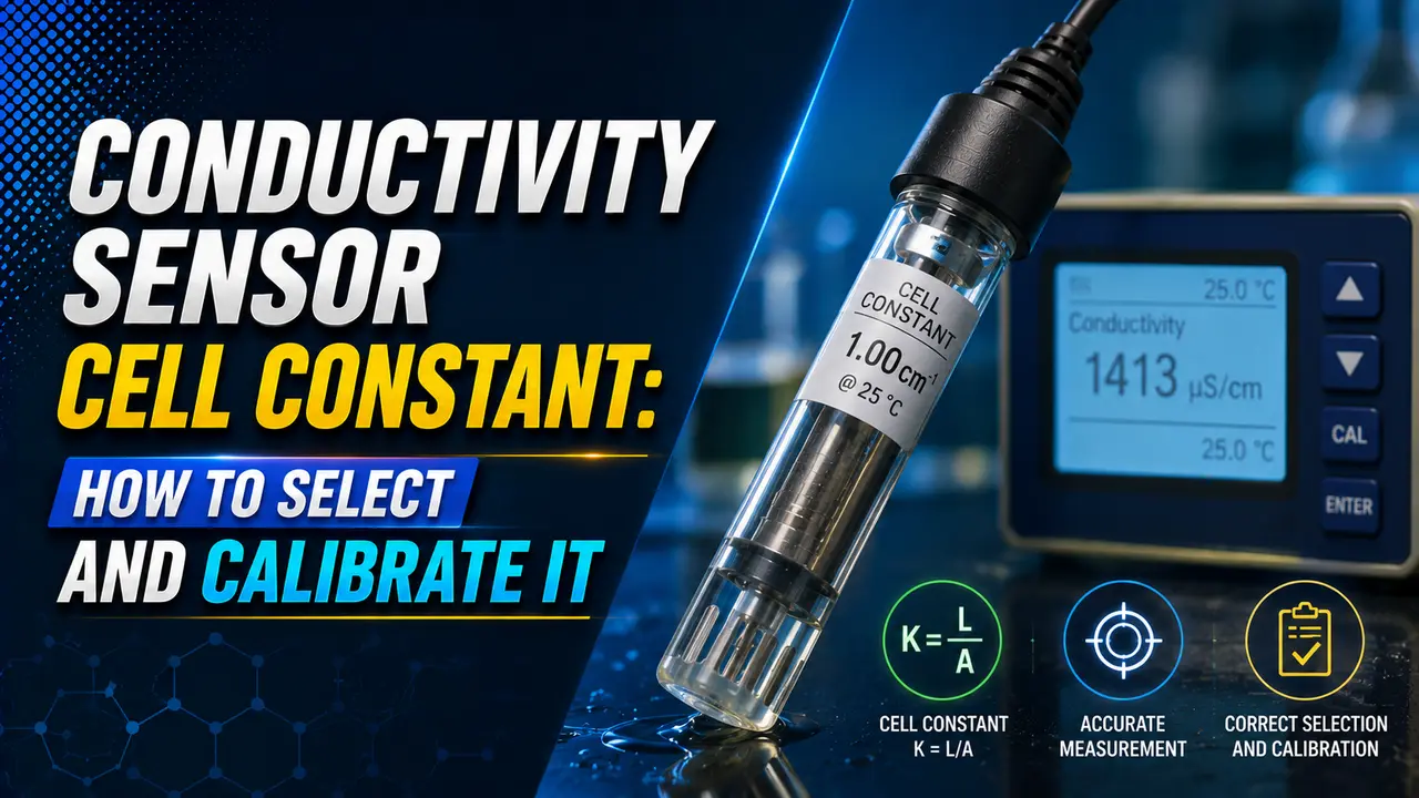
A conductivity sensor applies AC voltage between electrodes immersed in a liquid and measures the resulting current.
The measured value depends on electrode size and spacing as well as the liquid. The cell constant corrects for this geometry effect.
The cell constant (K) normalises readings for electrode geometry. The temperature compensation factor corrects for the temperature dependence of conductivity.
The polarisation effect causes error when the K value does not match the process range. Click any term above to expand.
How to Select the Right Cell Constant for Your Application
The cell constant must match the conductivity range of the process. Too large a K gives a noise-dominated signal. Too small a K causes polarisation error at high conductivity.
See the conductivity sensor guide for how the sensor converts current to conductivity.
| Conductivity Range | Typical Application | Recommended Cell Constant | Electrode Type |
|---|---|---|---|
| 0.05 to 20 µS/cm | Ultrapure water, pharmaceutical water for injection (WFI), semiconductor rinsing | 0.01 cm⁻¹ | 2-electrode platinum or titanium |
| 1 to 200 µS/cm | Demineralised water, boiler feedwater, condensate return | 0.1 cm⁻¹ | 2-electrode platinum or stainless steel |
| 10 µS/cm to 2 mS/cm | Drinking water, cooling tower makeup, RO permeate | 1.0 cm⁻¹ | 2-electrode or 4-electrode stainless steel or graphite |
| 1 mS/cm to 200 mS/cm | Process water, acids, bases, CIP solutions, wastewater | 10 cm⁻¹ | 4-electrode stainless steel or graphite, or toroidal |
| 10 mS/cm to 2 S/cm | Concentrated acids and bases, seawater, brine, electroplating baths | 50 to 100 cm⁻¹ | Toroidal (electrodeless) sensor only |
Formula and Worked Example
L: distance between electrode plates (cm)
A: surface area of each electrode plate (cm²)
G: measured conductance in mS (raw sensor output before geometry correction)
σ: specific conductivity in mS/cm (the reported process value)
Example: sensor plates 0.5 cm apart, each 0.5 cm² area.
K = 0.5 / 0.5 = 1.0 cm⁻¹
If measured conductance G = 1.45 mS, then σ = 1.45 × 1.0 = 1.45 mS/cm
In practice, the analyser multiplies automatically once K is programmed. The user sees only the specific conductivity in mS/cm or µS/cm. See the 4-20 mA signal guide for how the transmitter outputs this value.
How to Calibrate the Conductivity Sensor Cell Constant
There are two accepted methods for calibrating the cell constant: using a certified KCl standard solution, or using a reference meter on the same process sample. The KCl method is the traceable, recommended approach for industrial instruments.
Step 1: Prepare the KCl Standard Solution
KCl standards are available at certified conductivity values: 84 µS/cm (0.01 mol/L at 25°C), 1,413 µS/cm (0.1 mol/L at 25°C), and 12,900 µS/cm (1 mol/L at 25°C).
Choose the standard closest to your process conductivity range.
Step 2: Rinse the Sensor
Rinse the sensor three times with deionised water, then once with the KCl standard. This prevents contamination of the standard from process residue. Allow the sensor to equilibrate for 2 minutes in the standard.
Step 3: Measure Temperature and Correct to 25°C
Record the temperature of the standard. The certified KCl value applies at 25°C exactly. If your environment differs, use the certificate temperature correction table or activate the analyser temperature compensation during calibration.
Step 4: Adjust the Cell Constant
Enter calibration mode, immerse the sensor in the standard, and allow the reading to stabilise. Adjust K until the displayed conductivity matches the certified value. Save and record the new K. See the correction factor guide.
Conductivity Cell Constant Calculator
Where Cell Constant Selection Makes a Critical Difference
Pharmaceutical Ultrapure Water
USP and EP standards require conductivity below 1.3 µS/cm at 25°C for WFI. Only a K = 0.01 cm⁻¹ sensor has sufficient resolution at this level.
See the pH sensor guide for complementary water quality measurement.
Boiler Water and Condensate
Boiler feedwater conductivity typically ranges from 5 to 500 µS/cm. A K = 0.1 cm⁻¹ sensor gives high resolution in this range. Condensate return monitoring detects cooling water ingress early. A sudden conductivity rise signals a condenser tube leak before corrosion damage becomes severe.
CIP (Clean-in-Place) Monitoring
CIP circuits cycle between water, caustic (up to 100 mS/cm), and acid. A toroidal sensor at K = 10 to 25 cm⁻¹ handles the full range.
CIP conductivity monitoring confirms cleaning solution concentration and rinse completion.
Cooling Tower and Reverse Osmosis
Cooling tower blowdown (1 to 5 mS/cm) and RO reject (up to 15 mS/cm) use K = 1.0 or K = 10 cm⁻¹ sensors. RO permeate monitoring uses K = 0.1 cm⁻¹. See the conductivity sensor guide.
Watch: Cell Constant Determination and Conductivity Cell Calibration
Questions About Conductivity Cell Constant
External References
- Understanding Conductivity Cell Constants: Selection Guide -- Sensorex (updated 2025)
- Conductivity Probe Cell Constants Explained -- Atlas Scientific (updated 2026)
What We Learn Today
- Cell constant K = L/A (electrode gap divided by electrode area, in cm⁻¹). Specific conductivity = measured conductance × K.
- Select K = 0.01 for ultrapure water, K = 0.1 for demineralised water, K = 1.0 for process and drinking water, K = 10 for acids and bases, K = 50 to 100 for concentrated solutions.
- Conductivity changes approximately 2% per °C. Temperature compensation normalises all readings to 25°C for meaningful comparison.
- Calibrate using certified KCl standard solution. Choose the standard concentration closest to your process conductivity range.
- Rinse the sensor with deionised water then with the standard, allow 2 minutes to equilibrate, then adjust K until the reading matches the certified value.
- Use a toroidal (electrodeless) sensor above 20 mS/cm to avoid polarisation error and electrode fouling in high conductivity or coating applications.