
Changing transformer turns while full load current flows, without a single interruption, is a clever piece of engineering.
An on load tap changer adjusts the turns ratio of a power transformer while it carries load. It keeps the secondary voltage within limits as supply voltage and load change during the day.

What Is an On Load Tap Changer?
An on load tap changer, or OLTC, is a switching device that moves the transformer connection between winding taps while the unit stays energized. Changing taps changes the turns ratio and secondary voltage.
Grid voltage rises at night and falls at peak load, and long feeders add their own drop. Without regulation, customers would see voltages swing well outside acceptable limits.
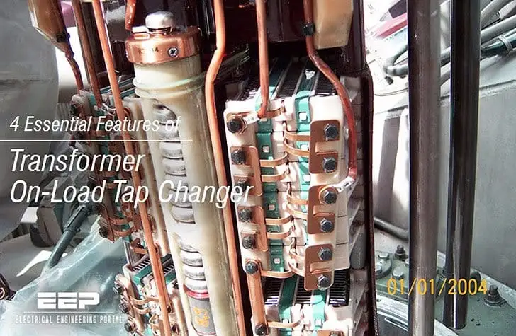
A typical OLTC provides a range of about plus and minus 10 percent in steps of 1.25 or 1.5 percent. Designs offer roughly 17 to 33 positions depending on the transformer.
Off circuit tap changers are cheaper but can only be moved when the transformer is switched off. They suit distribution transformers where seasonal adjustment is enough.
4 Vital Parts of the Tap Changer
The golden rule is that load current must never be interrupted during a tap change. The transition impedance briefly bridges two taps so current always has a path.
Resistor type OLTCs, common in Europe and India, switch very quickly. Reactor type designs, common in North America, can stay bridged between taps for extra positions.
Tap Change Sequence
The tap winding is usually on the high voltage side. Current is lower there, which reduces contact stress, and the outer winding makes tap leads easier to bring out.
Modern units often use vacuum interrupters in the diverter. Arcing then happens inside sealed bottles, so the oil stays clean much longer and maintenance intervals stretch.
Tap Step Formula With a Worked Example
Steps needed = Required change ÷ Step size
Worked example, 33 kV to 11 kV transformer:
Supply falls to 95 percent, so 31.35 kV
Secondary without correction = 10.45 kV
Required raise = 11 ÷ 10.45 = 1.0526, about 5.26 percent
Step size = 1.25 percent
Steps = 5.26 ÷ 1.25 ≈ 4 steps, giving about 10.98 kV
Rounding to whole steps leaves a small residual error. That is why automatic regulators use a deadband slightly larger than half a step.
Supply variations like these relate closely to voltage sag and swell events. The OLTC handles slow changes, not fast sags.
Automatic Voltage Regulator Control
An automatic voltage regulator measures secondary voltage through a VT and compares it with a set point. If the error stays outside the deadband for longer than a time delay, it issues a raise or lower command.
The time delay stops the tap changer hunting on short voltage swings. A typical first step delay is in the range of tens of seconds, with shorter delays for following steps.
Line drop compensation can raise the set point with load current to hold voltage at a remote point. Parallel transformers need master follower or circulating current control to keep taps in step, and results are often logged in SCADA.
OLTC vs Off Circuit Tap Changer
| Feature | OLTC | Off Circuit Tap Changer |
|---|---|---|
| Operation | Under load | Only when de energized |
| Range | About ±10 percent or more | Usually ±5 percent |
| Control | Automatic with AVR | Manual |
| Cost | High | Low |
| Maintenance | Regular inspection needed | Minimal |
| Typical use | Grid and industrial power transformers | Distribution transformers |
Choose an OLTC when supply or load voltage changes often during the day. For stable supplies, an off circuit changer set once per season is usually enough.
Tap range and step size are confirmed during routine tests, including ratio tests at every position.
Maintenance and Common Problems
NPC Electric notes that tap changer issues account for a large share of transformer failures. Follow the maker schedule for oil tests and inspections based on operation count and time.
The tap changer compartment usually has its own protective relay, separate from the main tank. It works alongside other protective relays on the transformer.
Tap Steps Calculator
Enter 105 to see the lower direction. Compare the final value with the regulator deadband to check that it will not hunt.
- Voltage regulation without interruption.
- Automatic control with AVR.
- Wide regulation range.
- Supports long feeders and variable loads.
- High cost and complexity.
- Regular maintenance required.
- Contact and oil wear with operations.
- Adds a potential failure point.
Reinhausen Tap Changer Technical Paper
Practical OLTC Explanation Video
Frequently Asked Questions on OLTC
Related Articles
- Transformer Turns Ratio and Secondary Voltage
- Transformer Routine and Type Tests
- Transformer Vector Group Explained
- Voltage Drop Explained
- Transformer kVA Rating Calculation
External References
- OLTC Technical Paper, Maschinenfabrik Reinhausen
- Features of Transformer OLTC, EEP
- OLTC Design Guide, NPC Electric
- Tap Changer, Wikipedia
What We Learn Today
- An OLTC changes transformer taps without interrupting load current.
- Selector, diverter, transition impedance and drive work in a fixed sequence.
- An AVR with deadband and delay controls taps automatically.