
Transformer Routine and Type Tests confirm a transformer meets its nameplate rating and design standard before it ever gets energized on site, catching manufacturing defects long before they become field failures.
Transformer Routine and Type Tests verify a unit against its nameplate rating and design standard before commissioning. Routine tests happen on every unit, type tests on a representative sample.
This builds naturally on Transformer Vector Group Explained, since a ratio and polarity test during routine testing is exactly where a wrong vector group would first get caught.
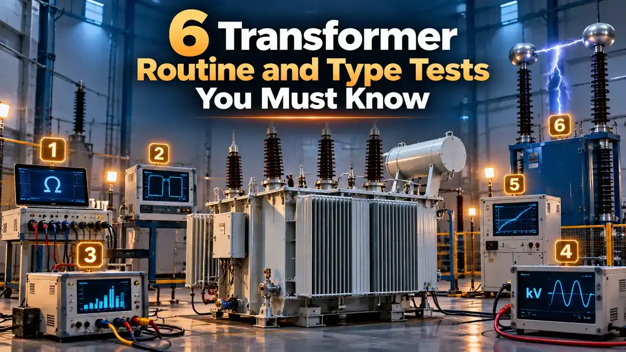
Transformer Routine and Type Tests
Every transformer leaving a factory goes through a defined sequence of electrical checks before it is accepted, and these checks fall into three broad categories under IEC 60076.
Routine tests are performed on every single unit manufactured, confirming basic performance and catching manufacturing defects before shipment.
Type tests are performed once on a representative unit from a design family, proving the design itself meets its rated performance rather than checking each individual unit.
Special tests sit beyond both categories, ordered only when a specific customer requirement or unusual application calls for extra verification beyond the standard test set.
None of these categories exist to catch the same thing twice. Routine tests focus on workmanship for that specific unit, while type tests focus on whether the underlying design itself was ever sound to begin with.
A transformer can pass every routine test and still belong to a design that never went through the relevant type test, which is exactly why buyers ask to see type test reports separately during procurement.
Test reports from an accredited laboratory carry more weight during procurement than an in house certificate, since an independent witness removes any question about how the results were obtained.
6 Routine Tests Performed on Every Unit

Common Type Tests
Confirms winding and oil temperature stay within design limits under sustained full load conditions.
Applies a steep, short duration high voltage surge, confirming insulation survives a simulated lightning strike.
Applies a higher than rated voltage across windings to ground, confirming basic dielectric strength.
Confirms noise output stays within the specified limit, relevant for units near occupied spaces.
Typical Factory Test Sequence
Low voltage, non destructive checks always come first. Higher voltage dielectric tests are deliberately scheduled last, after the winding is already confirmed sound electrically.
Correcting Winding Resistance for Temperature
Winding resistance readings change with temperature, so measurements taken on different days need correction to a common reference temperature before they can be compared fairly.
Skipping this correction step is a common source of confusion during commissioning, when a resistance reading taken on a cold morning gets compared directly against a factory reading taken at a completely different ambient temperature.
Where T = 234.5 for copper, t1 = temperature at measurement, t2 = reference temperature
Example:
R1 = 0.850 ohms at t1 = 32 C
Reference t2 = 75 C
R2 = 0.850 × (234.5 + 75) divided by (234.5 + 32)
R2 = 0.850 × 309.5 divided by 266.5 = 0.987 ohms
Routine vs Type vs Special Tests
| Test Category | Performed On | Purpose |
|---|---|---|
| Routine Test | Every manufactured unit | Confirm that unit meets its nameplate rating |
| Type Test | One representative unit per design | Prove the design meets rated performance |
| Special Test | Only when specified by the customer | Verify a specific extra requirement or condition |
Where These Tests Matter Most
Common Mistakes During Transformer Testing
Comparing uncorrected resistance readings: treating a cold morning reading as directly comparable to a factory reading taken at a different temperature leads to false conclusions about winding condition.
Another common gap is relying only on Insulation Resistance Testing with a Megger and skipping a proper ratio test, which can leave a wrong tap position or a shorted turn completely undetected.
Routine Tests vs Type Tests, the Real Difference
Routine Tests
Confirm this specific unit was built correctly, repeated on every single transformer regardless of design maturity.
Type Tests
Confirm the underlying design performs as claimed, typically not repeated once a design has already passed once.
Resistance Temperature Correction Calculator
Reference Document
Watch: Overview of Transformer Testing
Transformer Routine and Type Tests FAQs
Related Articles on This Site
- Transformer Vector Group Explained
- How to Calculate Transformer Efficiency
- Insulation Resistance Testing with a Megger
- What Is Insulation, Electrical
- Single Line Diagram Symbols and How to Read One
External References
What We Learn Today
- Routine tests run on every transformer, while type tests prove a design once for the whole family.
- Low voltage checks always come before higher voltage dielectric tests in the standard sequence.
- Winding resistance readings must be corrected to a common reference temperature before comparison.