Indian electricians say 440 V, the standard says 415 V and IEC says 400 V, yet all three come from one √3 rule. Below we work through the phasor maths, the tolerance band behind the 440 V habit and a safe way to measure it.
Line voltage in a star connected supply is 1.732 times phase voltage, so a few volts of difference per phase moves the line figure between 400, 415 and 440 V. We cover the maths, the Indian standards and the field checks.
Why three phase voltage is 440V in India when the standard says 415 V?
Why three phase voltage is 440V comes from the √3 rule: line voltage equals 1.732 times phase voltage because the phases are 120° apart. India declares 240/415 V under IS 12360, and 415 V plus the old 6 percent supply tolerance gives about 440 V, which is the same as 254 V per phase. Example: 240 × 1.732 = 415.7 V and 254 × 1.732 = 439.9 V.
What Is the Real Reason Behind 440 V?
The answer to why three phase voltage is 440V is the √3 rule: line to line voltage is 1.732 times line to neutral voltage, so 254 V per phase gives 439.9 V. India actually declares 240/415 V, and 440 V is the upper end of that supply once tolerance is added.
- Line voltage = √3 × phase voltage = 1.732 × Vph in a balanced star system.
- 230 V gives 398.4 V, 240 V gives 415.7 V, 250 V gives 433.0 V and 254 V gives 439.9 V.
- IS 12360 lists 240/415 V for India, not 230/400 V.
- A 6 percent tolerance on 415 V gives 415 × 1.06 = 439.9 V.
If you are new to these terms, read our notes on single phase and three phase power first. The same ideas also explain the RMS values your meter shows.
How Is Line Voltage Calculated from Phase Voltage?
Line voltage is calculated by multiplying phase voltage by √3, which is 1.732. The factor appears because two phase voltages 120° apart are subtracted as phasors, not added as plain numbers.
VL = 2 × Vph × cos 30°
VL = √3 × Vph = 1.732 × Vph
Picture R, Y and B as three equal arrows spaced 120° apart. The meter reading between R and Y is the line joining two arrow tips, and geometry gives it a length of 2 × Vph × cos 30°.
Since cos 30° is 0.866, twice that value is 1.732, the square root of 3. Our guide on phase angle in AC circuits covers the phasor maths in more depth.
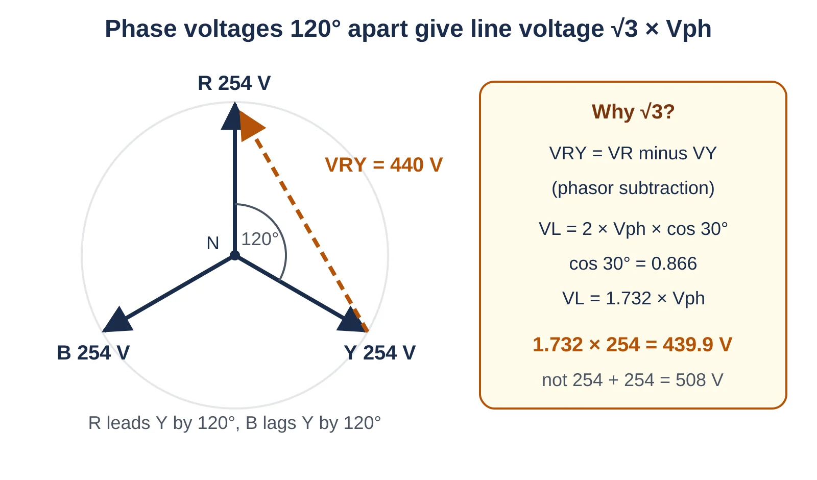
Adding 254 + 254 gives 508 V, but the two phases never peak together, so the real difference is only 439.9 V.
The Wikipedia article on three phase electric power states that line to line voltage is √3 times line to neutral voltage in a symmetrical star system. It lists red, yellow and blue as India's phase colours, hence R, Y and B.
Why Three Phase Voltage Is 440V When the Standard Says 415 V
The short reason why three phase voltage is 440V in everyday Indian speech is that 415 V plus its 6 percent tolerance lands at almost exactly 440 V. Transformer no load voltage and rounding did the rest.
IS 12360 from the Bureau of Indian Standards lists 240 V single phase and 415 V three phase as the preferred low voltages. Amendment 4 of November 2011 says the changeover from 240/415 V to the IEC style 230/400 V shall be kept in abeyance for the time being.
| Phase voltage | Line voltage (× 1.732) | Where you meet it |
|---|---|---|
| 230 V | 398.4 V (400 V) | IEC 60038 world standard |
| 240 V | 415.7 V (415 V) | IS 12360 declared value for India |
| 250 V | 433.0 V | Distribution transformer no load rating |
| 254 V | 439.9 V (440 V) | Upper end of 415 V plus 6 percent |
Rule 54 of the old Indian Electricity Rules 1956, since replaced by CEA safety regulations, limited low and medium voltage variation to 6 percent. So 415 × 1.06 = 439.9 V and 415 × 0.94 = 390.1 V, a healthy band of about 390 V to 440 V.
The same rules defined low voltage as not above 250 V and medium voltage as not above 650 V. That is why older Indian textbooks call the 415 V supply medium voltage.
When a site engineer says the panel is 440 V, read it as a 415 V nominal system. Size equipment for 415 V and confirm it tolerates 440 V on light load nights.
A Government e Marketplace catalogue for 11 kV distribution transformers lists the no load ratio as 11000/433 to 250 V with a nominal LV system of 415 V. The secondary starts high to cover the voltage drop in cables under load.
Why Is 3 Phase 400V and Not 690V?
Three phase supply is 400 V and not 690 V because voltages that are 120° out of step cannot simply be added. Only the vector difference between two phases appears across a load connected line to line.
Electrical Technology shows that two 230 V phasors 120° apart give 2 × 230 × sin 60° = 398 V, rounded to 400 V. A 690 V result would need all three phases to peak together, which would make them one phase.
Star vs Delta: Where Line and Phase Voltage Differ
In a star connection line voltage is √3 times phase voltage, while in a delta connection line voltage equals phase voltage. So the 440 V question applies to star connected secondaries, and nearly every LV distribution transformer in India has one.
Windings joined at a neutral point; 240 V line to neutral and 415 V line to line.
Windings form a closed triangle with no neutral; each winding sees the full 415 V.
Our comparison of star vs delta connection covers currents too, and the star delta transformation formula converts impedances.
- One transformer feeds both 3 phase motors at 415 V and single phase loads at 240 V.
- Winding insulation only needs to handle phase voltage to earth.
- A broken neutral can push 240 V loads toward 415 V and burn them.
- Line readings near 440 V stress older 400 V rated equipment.
What Voltage Tolerance Is Allowed on a 415 V Supply?
A 415 V supply in India was allowed to move by 6 percent either way under Rule 54, which gives a band of about 390 V to 440 V. IEC 60038 uses 230/400 V with a band of plus or minus 10 percent at the supply terminals.
The Schneider Electric Electrical Installation Guide lists India with both 400/230 V and 440/250 V entries and a frequency of 50 ± 1.5 Hz. So suppliers use the 440 V name as well, along with electricians.
IEC 60034 Zone A expects a motor to deliver rated output within plus or minus 5 percent of rated voltage. Check the motor nameplate details before connecting a 400 V motor to a panel that reads 440 V at night.
Unequal phase voltages hurt motors even more than a high average, as our article on voltage unbalance in motors shows with a numeric example.
Under the Indian Electricity Rules 1956, high voltage supply was allowed 6 percent on the higher side but 9 percent on the lower side. Extra high voltage was allowed 10 percent higher and 12.5 percent lower.
Line Voltage Calculator and Solved Example
Enter a phase voltage to get line voltage, or set phase to 0 and enter a line voltage to get phase voltage. The tolerance field shows the healthy band.
Vph = 254 V, tolerance 6 %
VL = 1.732 × 254 = 439.9 V
Low limit = 439.9 × 0.94 = 413.5 V
High limit = 439.9 × 1.06 = 466.3 V
Reverse: 415 ÷ 1.732 = 239.6 V
This is the same maths as the free line and phase voltage calculator on our sister site. Once you know line voltage, use our guide on how to calculate three phase power to get kW from current and power factor.
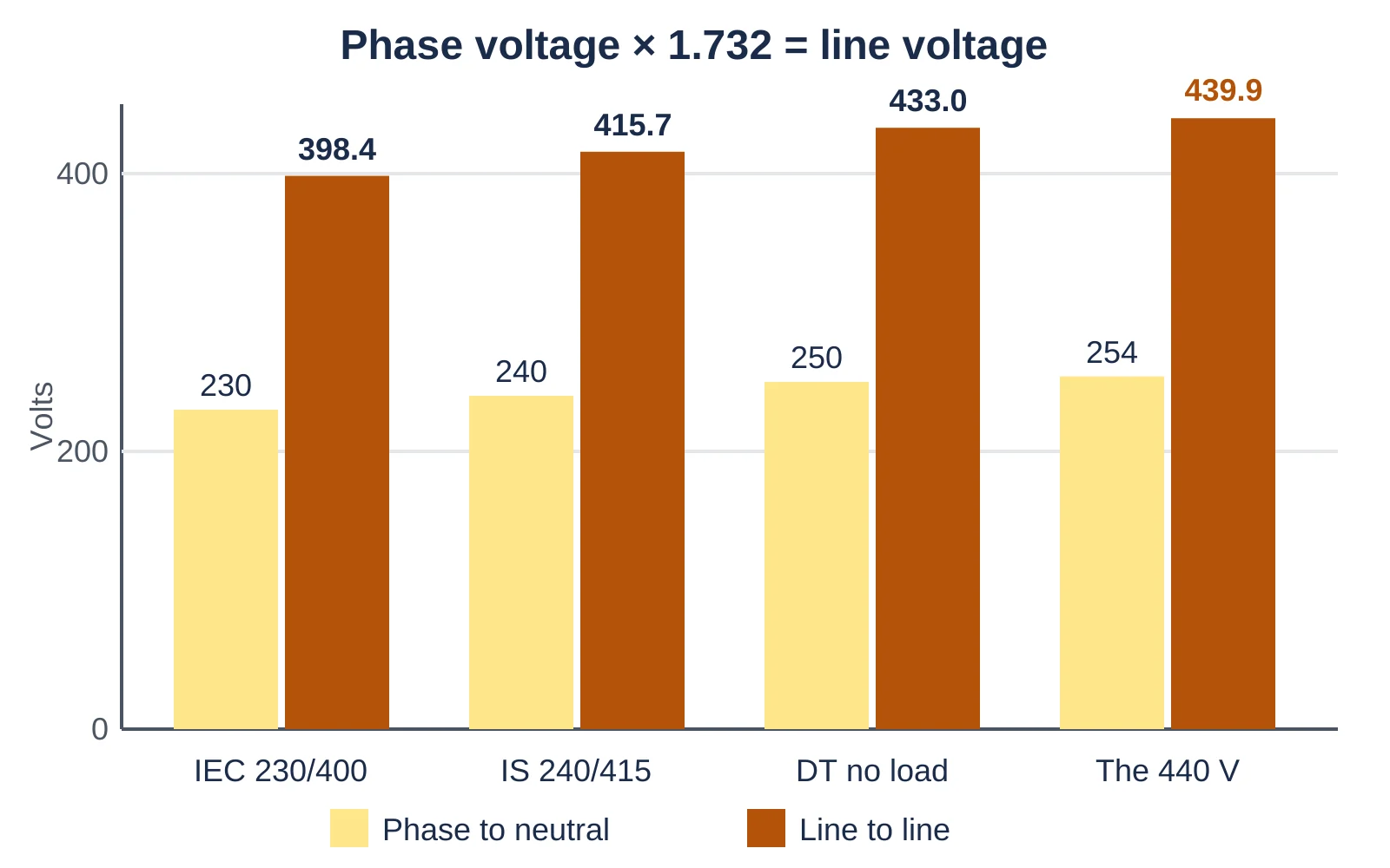
A rise of only 24 V per phase, from 230 V to 254 V, lifts the line voltage by 41.5 V, from 398.4 V to 439.9 V.
How to Measure Line and Phase Voltage with a Multimeter
Measure line voltage between two phases and phase voltage between a phase and neutral, using a CAT III meter on AC volts. Healthy Indian readings are about 415 V and 240 V, with line close to 1.732 times phase.
Wear arc rated PPE chosen from our electrical PPE selection guide and work under an approved permit. A slipped probe on a busbar can start an arc flash.
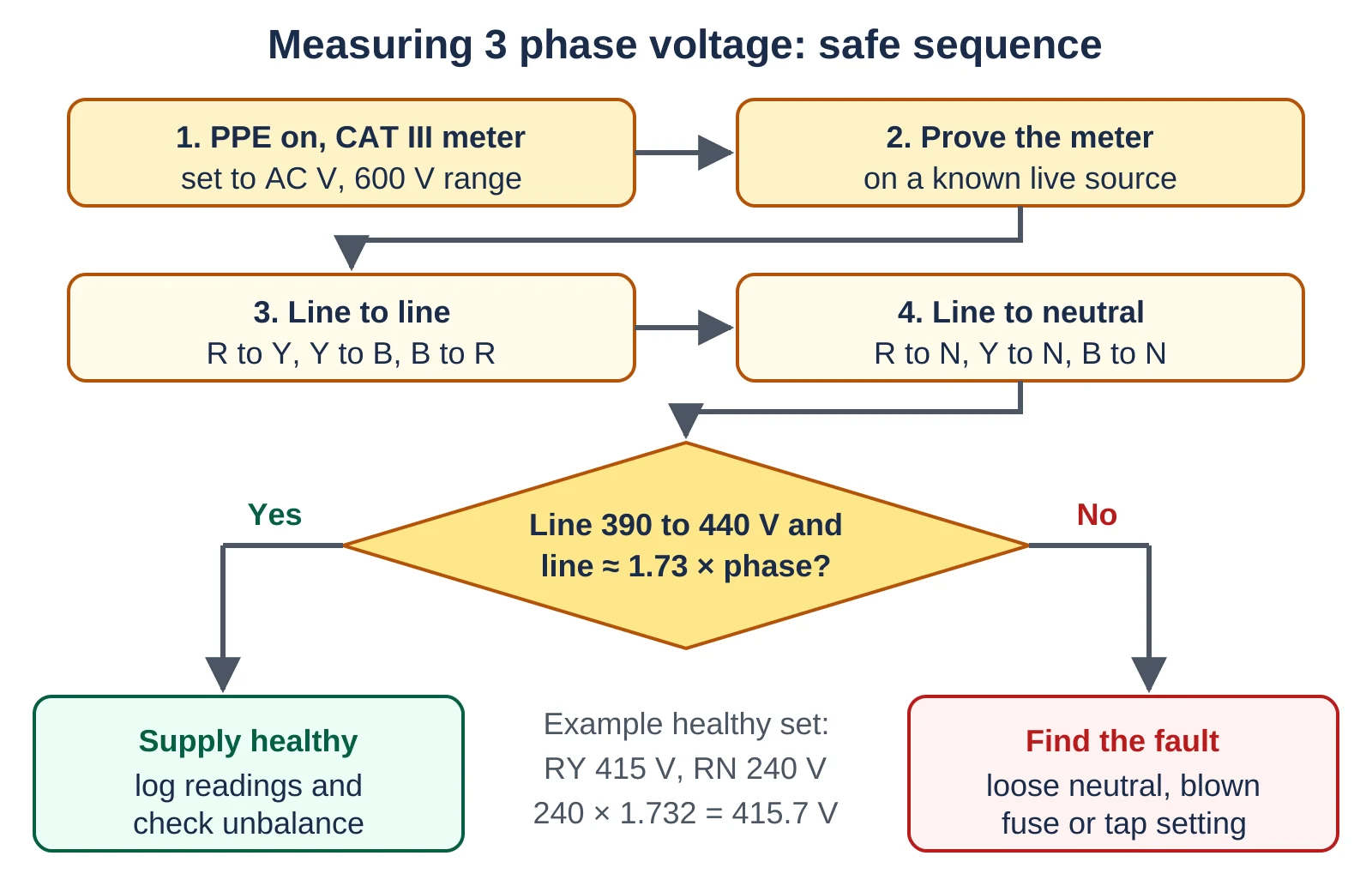
If neutral to earth voltage is more than a few volts, check the earthing too, as our page on TN, TT and IT earthing systems explains.
Log the six readings with time and load. A panel that reads 440 V at 2 AM and 400 V at noon points to tap settings and feeder loading.
Before any panel test, run through our electrical safety audit checklist so you confirm isolation points, earthing and PPE in writing.
Troubleshooting Wrong Three Phase Voltage Readings
Most wrong readings come from a loose neutral, a blown fuse, a wrong transformer tap or a meter on the wrong range. The table gives the likely cause for each symptom and what to check.
| Symptom | Likely cause | Check |
|---|---|---|
| Line 440 V or more at night | High tap, light load, capacitors on | Tap position, APFC relay steps |
| One phase 280 V, another 190 V | Loose or broken neutral | Neutral link torque, neutral current |
| One line reading near 240 V | Blown fuse or open phase | Fuse continuity, breaker contacts |
| All lines below 380 V at full load | Undersized cable, high drop | Voltage at source and load end |
A dip lasting seconds may be a sag rather than steady low voltage; see voltage sag, swell and flicker.
- Line readings within about 390 V to 440 V on a 415 V system.
- Phase readings within about 225 V to 255 V on a 240 V system.
- No two line readings differ by more than about 2 percent.
For the theory behind the transformer side, the transformer working principle page explains turns ratio and regulation. Our own note on turns ratio and secondary voltage shows how 11000/433 V maps to 250 V per phase.
Why Three Phase Voltage Is 440V FAQ
Line voltage is measured between two lines, while phase voltage is measured between one line and neutral.
In a star supply with 240 V phase voltage, the line voltage is 1.732 × 240 = 415.7 V, which Indian panels label as 415 V.
The declared value is 240/415 V under IS 12360, but 415 V plus 6 percent tolerance gives about 440 V.
Light loading at night and 433 V transformer secondaries often push readings near 440 V, so the 440 V name stuck on site.
Multiply the phase voltage by √3, which is 1.732, because two phasors 120° apart give 2 × Vph × cos 30°.
For example, 254 V phase voltage gives 1.732 × 254 = 439.9 V, and 230 V gives 398.4 V.
The most common mistake is using a low category meter or the wrong range on a live distribution board.
Always use a CAT III 600 V meter on AC volts, prove it on a known source and measure all six readings.
Choose a motor rated 415 V, because IEC 60034 Zone A expects rated output within 5 percent of rated voltage.
A 400 V motor on a supply that reaches 440 V runs 10 percent high, which raises magnetising current and heating.
Related Articles
- Single Phase vs Three Phase Power
- Star vs Delta Connection
- How to Calculate Three Phase Power
- Voltage Unbalance Calculation for Motors
- Transformer Vector Group
External References
- Indian Electricity Rules 1956, Rule 54 declared voltage (PDF)
- Electrical Technology: If a 1 Phase Supply is 230V, Why is 3 Phase 400V and Not 690V
- Wikipedia: Three phase electric power
What We Learn Today
- Line voltage equals 1.732 times phase voltage in a star system because two phasors spaced 120° apart subtract as vectors rather than adding.
- The familiar 440 V figure in India is simply 415 V plus the old 6 percent supply tolerance, which equals 439.9 V or 254 V per phase.
- Measure line and phase voltage with a CAT III meter, record all six readings and check that line readings are 1.732 times phase readings.