
A few volts of difference between the three phases looks harmless on a panel meter, yet it can push motor current and winding temperature far above normal. This guide shows how to calculate the problem, read the limits and fix it in the field.
Unequal phase voltages make 3 phase motors run hot, noisy and short lived. Learn how voltage unbalance is calculated, what the NEMA and IEC limits mean and how to bring it back under control.

What Is Voltage Unbalance?
Voltage unbalance is the condition in a 3 phase supply where the three line voltages are not equal in magnitude, or are not spaced exactly 120 degrees apart. A perfectly balanced system, as explained in single phase vs three phase power, has three equal sine waves shifted by one third of a cycle.
In real plants the voltages are never perfectly equal, because single phase loads, cables and transformers are never perfectly matched. The small difference becomes important when it feeds an AC induction motor, which reacts to it with a much larger difference in current.
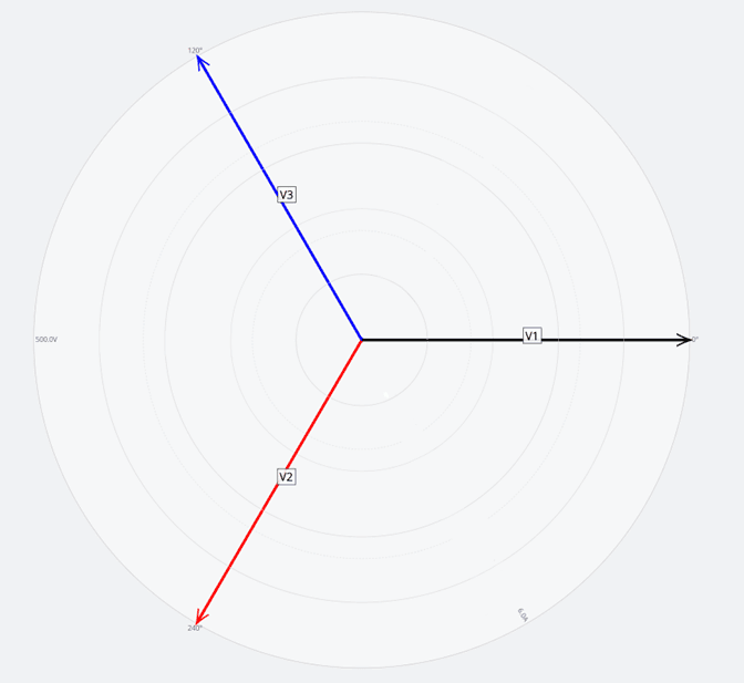
The diagram shows the ideal case with three equal phasors. Any change in the length or angle of one phasor creates an unbalanced set, which can be split into positive, negative and zero sequence parts.
Two Ways to Define the Unbalance
Engineers use two common definitions, and they give slightly different numbers. Knowing which one a meter or relay uses avoids arguments during commissioning.
Maximum deviation of any line voltage from the average, divided by the average, times 100. It needs only a multimeter.
Ratio of negative sequence voltage to positive sequence voltage, times 100. It uses symmetrical components.
The NEMA method, also used in ANSI C84.1, works with line to line readings and ignores angles. The IEC method is closer to the physics, because the negative sequence voltage is what actually creates a reverse rotating field inside the motor, a topic linked to phase angle in AC circuits.
A few percent of negative sequence voltage drives a large negative sequence current, because the motor offers it roughly its locked rotor impedance. That is why small voltage differences cause large current differences.
Voltage Unbalance Formula With Worked Example
IEC: VUF % = 100 × (V2 ÷ V1)
From line voltages a, b, c: β = (a⁴ + b⁴ + c⁴) ÷ (a² + b² + c²)²
VUF = 100 × √((1 minus √(3 minus 6β)) ÷ (1 + √(3 minus 6β)))
Example, 415 V Indian plant supply:
Vry = 415 V, Vyb = 408 V, Vbr = 400 V
Average = (415 + 408 + 400) ÷ 3 = 407.67 V
Maximum deviation = 407.67 minus 400 = 7.67 V
NEMA unbalance = 100 × 7.67 ÷ 407.67 = 1.88 %
IEC VUF = 2.13 %
Heating rise ≈ 2 × (1.88)² = 7.07 %
Notice that the IEC value is higher than the NEMA value here, so near a 2 percent limit the chosen definition of voltage unbalance can change the verdict.
The heating rule, temperature rise in percent equals two times the square of the percent voltage unbalance, is the NEMA rule of thumb. It tells you that the extra heat grows with the square, so doubling the unbalance roughly quadruples the extra heating in the motor insulation class system.
Voltage Unbalance Calculator for 3 Phase Supply
Enter three readings taken at the motor terminals with a true RMS meter under normal load. Readings at the main incomer can hide voltage unbalance created by a weak joint or long feeder, see voltage drop calculation.
Take all three line readings within a few seconds of each other with the same meter. Load changes between readings can create a false voltage unbalance that disappears when you measure again.
Second Example From an ABB Technical Note
ABB uses an example with measured line voltages of 460 V, 467 V and 450 V. The average is 459 V, the largest deviation is 9 V, and the NEMA result is 100 × 9 ÷ 459 = 1.96 percent.
The calculator gives an IEC factor of about 2.15 percent. ABB also notes that variable speed drives are usually allowed only about 3 percent at their input, because unbalance creates even larger current unbalance in the rectifier and DC bus capacitors.
How Unbalanced Voltage Hurts an Induction Motor
The negative sequence voltage produces a magnetic field that rotates opposite to the rotor. The rotor sees it at almost twice supply frequency, so large currents heat the rotor bars.
Power Monitors explains that NEMA treats less than 1 percent as ideal and more than 2 percent as unacceptable, and that a motor should not run at all when unbalance reaches 5 percent. In its example, a 3.13 percent voltage unbalance produced 22 to 24 percent current unbalance at full load.
The same white paper reports about 19.6 percent temperature rise for that case, cutting winding life by about a quarter. Each 10 °C above rated temperature roughly halves insulation life, which is why thermal overload relays sized for balanced current may not protect a motor running on unbalanced voltage.
At locked rotor, the same 3.13 percent unbalance produced only 3 to 6 percent current unbalance in the Power Monitors example. The effect is largest at no load and light load, where the negative sequence current is large compared with the normal current.
NEMA MG1 Motor Derating Table
| Voltage Unbalance, % | Approximate Derating Factor | Practical Meaning |
|---|---|---|
| 0 to 1 | 1.00 | Full nameplate output |
| 2 | about 0.95 | Load the motor to 95 percent |
| 3 | about 0.88 | Load the motor to 88 percent |
| 4 | about 0.82 | Consider a larger motor |
| 5 | about 0.75 | Operation not recommended |
The factors come from the NEMA MG1 derating curve. For example, a 30 kW motor on a 3 percent supply should carry about 30 × 0.88 = 26.4 kW, a useful check alongside the motor full load current calculation.
For IEC motors used in India, IEC 60034 1 states that a motor should work with a negative sequence component up to 1 percent continuously, or 1.5 percent for a few minutes. Beyond that, the designer must derate, a point to note along with IEC 60034 efficiency classes when choosing a motor.
Common Causes of Phase Voltage Imbalance
A blown fuse in one leg of an APFC panel is a classic hidden cause, because the panel still shows a good power factor on the healthy phases. Loose joints show up clearly in infrared thermography of electrical panels, long before they fail.
When unbalance appears only at certain times of day, log it with a power quality analyser for a full week. The pattern usually points to a particular single phase load that switches on and off.
7 Proven Fixes for Voltage Unbalance
Most voltage unbalance problems inside a factory are solved by the first four fixes. If the voltage unbalance is present at the incoming supply, talk to the utility with logged data, and meanwhile protect motors with suitable motor protection relays.
An input line reactor helps a variable speed drive tolerate supply unbalance, as ABB recommends. It also reduces the input current harmonics described in THD calculation in power systems, which often appear together with unbalance.
Measuring Supply Imbalance in the Field
- Use a calibrated true RMS meter or a class A power quality analyser.
- Measure line to line voltages at the motor terminal box.
- Record all three readings at the same moment and same load.
- Measure the three motor currents with a clamp meter.
- Rotate the supply leads one position and see if the high current follows the supply or the motor.
- Log at least one week to capture daily load patterns.
- Compare results with NEMA, IEC 60034 1 and EN 50160 limits.
The lead rotation test separates a supply problem from a motor problem. If the high current stays with the motor winding, check the motor using the insulation resistance test and winding resistance readings.
Standards and Limits at a Glance
| Standard | Quantity | Typical Limit |
|---|---|---|
| NEMA MG1 | Motor terminal unbalance | Derate above 1 %, avoid above 5 % |
| ANSI C84.1 | Supply at meter, no load | 3 % maximum |
| IEC 60034 1 | Negative sequence at motor | 1 % continuous, 1.5 % short time |
| EN 50160 | Public LV supply, 10 minute values | 2 % for 95 % of the week |
| Drive makers | VFD input | About 3 % |
Utility limits in India are set by the state regulator and grid code. Voltage unbalance is best logged with an analyser that also records voltage sag, swell and flicker.
- Lower motor winding and rotor temperature.
- Longer insulation and bearing life.
- Fewer nuisance trips on drives and relays.
- Lower losses in cables and transformers.
- Utility side unbalance is outside plant control.
- Load rebalancing changes as loads change.
- Line reactors add cost, space and losses.
- Derating means buying a larger motor.
Protection Relays for Negative Sequence
Numerical motor relays include an unbalance or negative sequence element, ANSI code 46, which trips when the negative sequence current stays high. A phase reversal or phase voltage element, ANSI code 47, blocks starting when the supply sequence or balance is wrong, as described in protective relays explained.
Set the unbalance alarm below the trip level so maintenance staff get early warning, then fine tune both settings using the motor maker data.
ABB Technical Note PDF
Video: Motor Voltage and Current Unbalance
Voltage Unbalance FAQ
It is a condition where the three line voltages of a 3 phase supply are not equal or not 120 degrees apart. Even a difference of a few volts matters for motors.
It is expressed as a percentage, using either the NEMA method or the IEC negative sequence method. The two methods give close but not identical values for the same supply, so always state which one you used.
Find the average of the three line voltages and the largest deviation of any one voltage from that average. Divide the deviation by the average and multiply by 100.
For readings of 415, 408 and 400 volts, the average is 407.67 volts and the largest deviation is 7.67 volts. The result is therefore about 1.88 percent, which is close to the NEMA warning level.
It is the negative sequence voltage divided by the positive sequence voltage, expressed in percent. Power quality analysers calculate it from phase magnitudes and angles.
You can also find it from three line voltages with the beta formula shown in this article. For the 415 volt example it gives about 2.13 percent, slightly above the NEMA value of 1.88 percent.
NEMA treats below 1 percent as ideal and above 2 percent as unacceptable without derating. Operation above 5 percent is not recommended at all.
IEC 60034 1 allows a negative sequence component of 1 percent continuously. Short periods up to 1.5 percent are allowed for a few minutes, after which the motor must be derated or the supply corrected.
The negative sequence voltage creates a reverse rotating field that the motor opposes with low impedance. Large negative sequence currents then flow and heat the rotor and stator.
NEMA estimates the extra heating as about two times the square of the percent unbalance. So 3 percent unbalance gives roughly 18 percent extra temperature rise in the windings.
Use the NEMA MG1 curve, which gives about 0.95 at 2 percent and 0.88 at 3 percent. At 5 percent the factor falls to about 0.75.
Multiply the motor rating by the factor to find the safe continuous load. A 30 kW motor on a 3 percent supply should therefore carry no more than about 26.4 kilowatts.
Inside a plant, most voltage unbalance comes from uneven single phase loads, hot joints and blown capacitor fuses, so fix those first. Then check transformer taps and replace open delta banks.
Protect important motors with relays that have an unbalance trip. Fit line reactors on drives, and share week long logged data with the utility whenever the source itself is unbalanced.
Related Articles
- Motor Protection Relay Types
- How an AC Induction Motor Works
- Thermal Overload Relay Explained
- Harmonic Distortion THD Calculation in Power Systems
- Voltage Sag, Swell and Flicker Explained
External References
- Three Phase Voltage Imbalances, How Do I Calculate Them, ABB
- Voltage Unbalance and Polyphase Induction Motors, Power Monitors
- Symmetrical Components, Wikipedia
What We Learn Today
- Voltage unbalance is the maximum deviation from the average line voltage divided by the average, or the negative to positive sequence ratio in the IEC method.
- NEMA treats under 1 percent as ideal and over 2 percent as unacceptable, while IEC 60034 1 allows 1 percent negative sequence continuously for motors.
- Extra motor heating is roughly two times the square of the percent unbalance, so motors need derating to about 0.88 at 3 percent.