
Circuits with several sources do not need to be solved all at once. Analyze the effect of one source at a time, add the results together, and the answer comes out exactly right. Here is exactly how Superposition Theorem works, with a real solved example and a live calculator you can try right now.
What Is the Superposition Theorem?
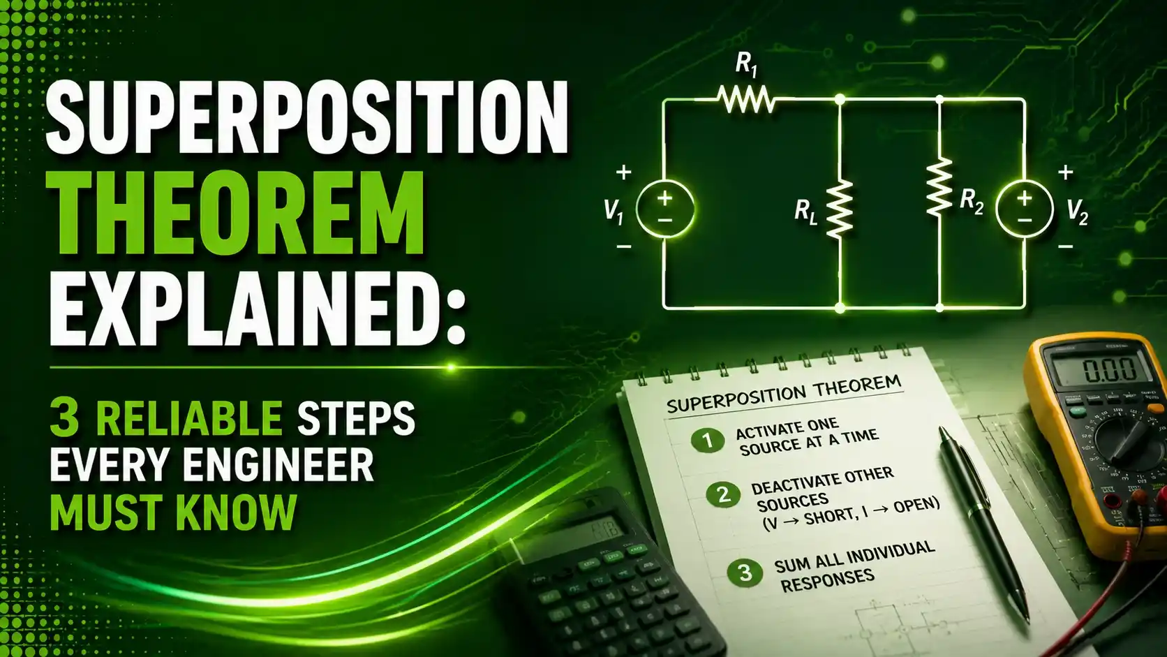
The Superposition Theorem states that in any linear circuit with multiple independent sources, the voltage or current at any point equals the algebraic sum of the contributions from each source acting alone, with every other independent source deactivated.
Rather than solving several simultaneous equations at once, this theorem lets you break a complicated multi-source circuit down into a series of much simpler single-source problems, then simply add the results together at the end.
This method builds on the same foundation as Kirchhoff's Current Law and Kirchhoff's Voltage Law, and complements the equivalent-circuit approach used in Thevenin's Theorem and Norton's Theorem.
This guide covers the three reliable steps behind this technique, with a real solved example you can follow from start to finish.

How the Superposition Theorem Simplifies a Circuit
Every application of this method follows the same repeating cycle, once for each independent source in the circuit.
Pick One Source to Activate
Choose a single independent source in the circuit and leave it in place.
Deactivate Every Other Source
Short every other independent voltage source, and open every other independent current source.
Solve for the Single-Source Response
Calculate the voltage or current of interest using only that one active source.
Repeat and Sum Algebraically
Repeat for every remaining source, then add all the individual results together.
3 Reliable Steps to Master the Superposition Theorem
These three ideas explain why the method works and where it genuinely cannot be applied.
Only Linear Circuits Qualify
Superposition depends entirely on linearity. Since resistors, inductors, and capacitors all behave linearly, the theorem works cleanly for standard passive circuits, but fails for circuits containing genuinely nonlinear elements like diodes.
Dependent Sources Are Never Deactivated
Independent sources get shorted or opened one at a time during analysis, but a dependent source always stays active in every single pass, since its value depends on another circuit variable rather than being fixed.
Superposition Never Applies Directly to Power
Power is proportional to the square of current or voltage, making it a nonlinear quantity. Adding up individual power contributions from superposition will not give the correct total power dissipated.
A Real Solved Example
Consider the same T-type circuit used across our Kirchhoff's law, Thevenin, and Norton guides: a 10V source and a 20V source, each feeding into a shared 40-ohm center resistor, R3, through their own 10-ohm and 20-ohm series resistors.
What is happening: With the 20V source shorted, only the 10V source drives current through the network, splitting between the 20-ohm and 40-ohm parallel branches, delivering 143mA through R3.
A real example: Restoring the 20V source and shorting the 10V source instead produces an identical 143mA through R3 in this particular circuit, purely by the specific resistor values chosen here.
Why it works: Since both individual currents flow in the same direction through R3, algebraically adding them together, rather than subtracting, gives the correct combined 286mA total.
Using Ohm's law on that combined current gives a voltage of 0.286A × 40Ω = 11.44V across R3, again matching every other analysis method applied to this same circuit. That consistency is exactly the point: superposition is not a shortcut that sacrifices accuracy, it is a genuinely equivalent path to the same correct answer.
The second example on the reference page swaps in a current source alongside a voltage source, and the same logic still holds. A 20V source contributes 4V across a shared resistor, an 8A current source contributes another 8V across that same resistor, and the two add together to a final 12V. Mixing source types changes nothing about the underlying method, only the specific deactivation rule applied to each type.
Superposition Formula
Written generally for a circuit with any number of independent sources, superposition reduces to one simple summation.
Total response: X = X1 + X2 + ... + Xn
Where each X_i is the response due to source i acting alone
Worked example: IR3(1) = 143mA, IR3(2) = 143mA
IR3 = 143 + 143 = 286mA
Try It: Two-Source Contribution Calculator
Enter two source voltages and the shared resistor network values to see each source's individual contribution and the combined total.
Superposition Theorem vs Other Analysis Methods
| Method | Best For | Practical Note |
|---|---|---|
| Superposition Theorem | Circuits with several independent sources | Avoids simultaneous equations entirely |
| Thevenin's Theorem | Testing multiple loads against one network | Reduces to a voltage source and resistor |
| Norton's Theorem | Circuits more natural in current form | Reduces to a current source and resistor |
| Mesh or Nodal Analysis | Very large, densely connected networks | Often faster than repeated superposition passes |
Applications of the Theorem
Audio Mixing Circuits
Analyzing each input signal's individual contribution to a mixed output stage.
AC and DC Combined Circuits
Separating a signal's AC and DC components for independent analysis.
Amplifier Bias Analysis
Separating DC bias conditions from AC signal behavior in transistor circuits.
Multi-Source Power Systems
Evaluating how each individual generator contributes to a shared bus voltage.
Interference and Noise Analysis
Isolating how each noise source individually affects a sensitive measurement point.
Educational Circuit Verification
Cross-checking answers from mesh or nodal analysis using an independent method.
What unites all six of these roles is the same underlying instinct: isolate one cause, measure its individual effect, then move on to the next cause. That instinct generalizes well beyond circuit theory too, but few other fields offer as clean a mathematical guarantee that the pieces really do add back up to the correct whole.
Advantages and Limitations of the Theorem
Why Superposition Is So Useful
Limitations to Keep in Mind
Download Superposition References
These two references go deeper into linearity and superposition in circuit analysis.
6.200 Notes: Using Linearity in Circuit Analysis
Official MIT lecture notes covering superposition and linearity
Superposition Theorem Module
Lessons in Electric Circuits reference module with worked examples
Watch: Superposition Theorem Explained
This video walks through the method step by step with solved examples.
FAQs on the Superposition Theorem
External References
- MIT 6.200, Using Linearity in Circuit Analysis
- Lessons in Electric Circuits, Superposition Theorem Module
- Electronics Tutorials, Superposition Theorem Tutorial
- YouTube, Superposition Theorem Explained, Step-by-Step with Solved Examples
What we learn today
- The Superposition Theorem finds the response at any point by adding together the contributions from each independent source acting alone.
- Only linear circuits qualify, since the method depends entirely on the mathematical properties of linearity.
- Dependent sources always stay active during every pass of the analysis, unlike independent sources which get deactivated one at a time.
- Superposition never applies directly to power calculations, since power is a nonlinear quantity.
- The method genuinely agrees with Kirchhoff's laws, Thevenin's Theorem, and Norton's Theorem when applied to the same circuit.