
An LED must never be connected straight across a supply, because its current rises steeply once the forward voltage is crossed. A single series resistor, sized with Ohm law, holds the current at a safe value and keeps the LED glowing for years.
LED resistor calculation takes one line of Ohm law, yet wrong values still burn LEDs and Arduino pins every day. This guide gives the formula, a forward voltage chart, solved examples for 5 V and 12 V, power rating rules and a calculator that rounds to standard values.
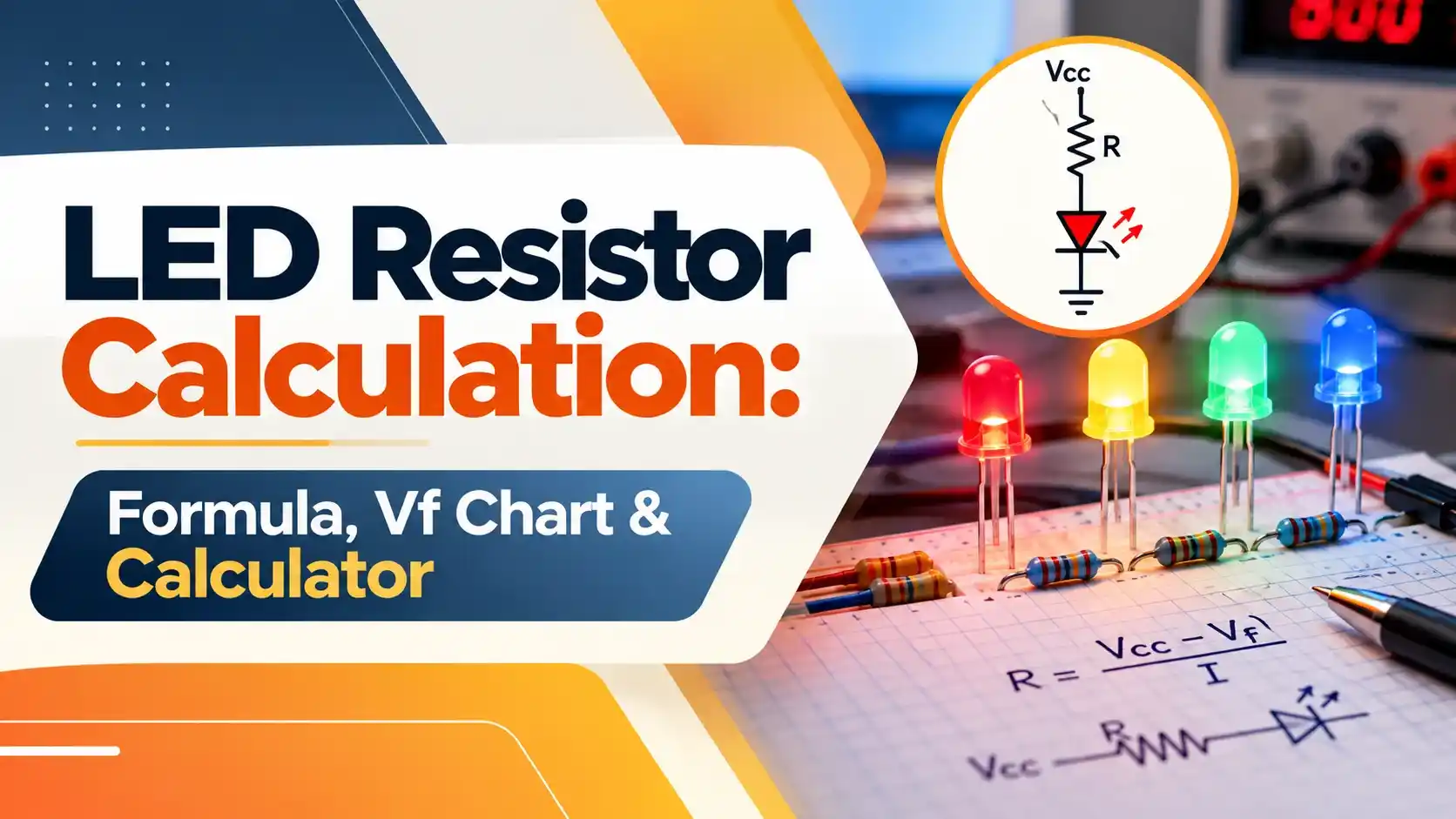
What Is LED Resistor Calculation?
LED resistor calculation finds the series resistance that drops the extra supply voltage and limits LED current to a safe value using R = (Vs minus Vf) ÷ If. For a red LED with 2 V forward drop on a 5 V supply at 20 mA, R = 3 V ÷ 0.02 A = 150 Ω.
- Formula: R = (Vs minus N × Vf) ÷ If, with If in amperes.
- Typical Vf: red 1.8 to 2 V, yellow and green about 2.1 V, blue and white about 3.3 V.
- Typical current: 10 to 20 mA for 5 mm indicator LEDs.
- Round up to the next standard E12 value, never down.
- Resistor power P = I² × R; choose a rating at least twice this.
The resistor is needed because an LED is a diode, not a lamp. As our guide to LED working principle shows, its current climbs very steeply once the forward voltage is reached, so even a small rise in supply voltage can destroy it.
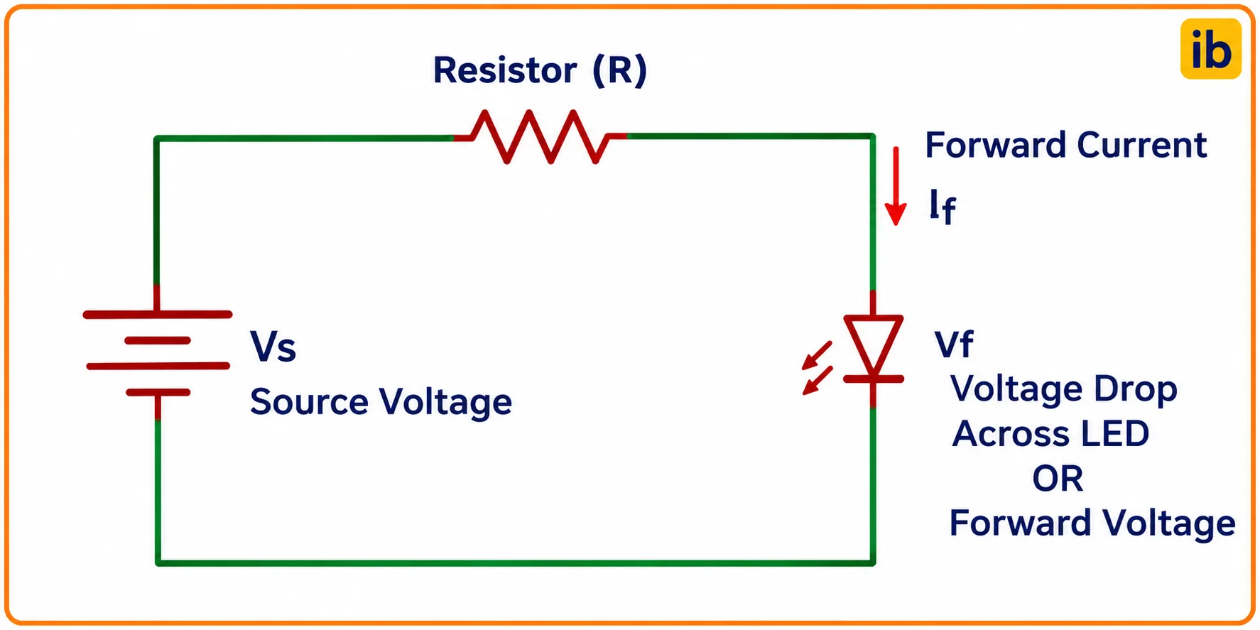
The circuit shows the supply, one series resistor and the LED in a single loop, so the same current flows through both parts. CircuitDigest suggests 2 V and 20 mA as default values when the LED datasheet is not available.
LED Resistor Calculation Formula
By Kirchhoff voltage law, the supply voltage equals the resistor drop plus the LED forward voltage. Applying Ohm law to the resistor alone gives the LED resistor calculation formula.
P = If² × R
Vs = supply voltage, Vf = forward voltage of one LED
N = LEDs in series, If = forward current in A
Solved example: 5 V, one red LED, Vf 2 V, 20 mA
R = (5 minus 2) ÷ 0.020 = 150 Ω
P = 0.020² × 150 = 0.06 W, use a 1/4 W resistor
SparkFun points out that the LED current, forward voltage and supply voltage are the only three values needed, and that milliamperes must be converted to amperes first. Forgetting this step is the most common reason for an answer a thousand times too small.
When the datasheet gives a range such as 1.8 to 2.2 V, use the lowest value in your LED resistor calculation. A lower Vf means more current, so designing for it keeps the LED safe in the worst case.
LED Forward Voltage Chart by Colour
Forward voltage depends on the semiconductor material, which also sets the colour. NextPCB lists these typical values at 20 mA and 25 °C for standard 5 mm LEDs.
| Colour | Typical Vf | Vf Range | Max If |
|---|---|---|---|
| Infrared | 1.2 V | 1.0 to 1.6 V | 100 mA |
| Red | 1.8 V | 1.6 to 2.2 V | 30 mA |
| Orange | 2.0 V | 1.8 to 2.3 V | 30 mA |
| Yellow | 2.1 V | 1.8 to 2.4 V | 30 mA |
| Green (standard) | 2.1 V | 1.9 to 2.4 V | 25 mA |
| Blue | 3.3 V | 3.0 to 3.6 V | 30 mA |
| White | 3.3 V | 3.0 to 3.6 V | 30 mA |
| UV | 3.5 V | 3.2 to 4.0 V | 20 mA |
Bright green LEDs made from InGaN behave like blue ones, near 3.2 V, so always check the datasheet. A typical red 5 mm LED datasheet such as the WP7113SRD lists 1.85 V typical and 2.5 V maximum at 20 mA, with a 5 V reverse voltage limit.
LED forward voltage falls by about 2 mV for every 1 °C rise in temperature. NextPCB notes that a red LED at 85 °C may drop from 2.0 V to 1.8 V, raising current by about 15 percent through a fixed resistor.
LED Resistor Calculator
Solved Example: Three LEDs on 12 V
Three red LEDs at 2 V each are wired in series on a 12 V supply at 20 mA. The total forward drop is 3 × 2 = 6 V, so R = (12 minus 6) ÷ 0.020 = 300 Ω, which is not an E12 value.
Next E12 value up = 330 Ω
Actual If = 6 ÷ 330 = 18.2 mA
P = 6² ÷ 330 = 0.109 W = 109 mW
2 × 10⁹ mW = 218 mW, use a 1/4 W resistor
Rounding up to 330 Ω gives 18.2 mA, slightly dimmer but still bright and much safer. The Boston University EK 307 lab handout gives the same rule: if the exact value is not available, take the next value up, such as 43 Ω for 42 Ω.
For resistor series and markings, see the resistor colour code guide. A 330 Ω E12 resistor is coded orange, orange, brown.
LED Resistor Value for 5 V and 12 V
The table below lists ready values from the LED resistor calculation for common supplies at 20 mA, already rounded up to E12. Use it as a quick reference on the bench, then confirm with the calculator for your exact LED.
| Supply | LED Colour (Vf) | Exact R | Use (E12) | Current |
|---|---|---|---|---|
| 5 V | Red (2.0 V) | 150 Ω | 150 Ω | 20.0 mA |
| 5 V | Blue or white (3.3 V) | 85 Ω | 100 Ω | 17.0 mA |
| 3.3 V | Red (2.0 V) | 65 Ω | 68 Ω | 19.1 mA |
| 12 V | Red (2.0 V) | 500 Ω | 560 Ω | 17.9 mA |
| 12 V | White (3.3 V) | 435 Ω | 470 Ω | 18.5 mA |
| 24 V | Green (2.1 V) | 1095 Ω | 1.2 kΩ | 18.3 mA |
For 24 V PLC indicator outputs the drop is large, so check the resistor power too. At 18.3 mA through 1.2 kΩ the resistor dissipates about 0.40 W, so a 1 W part runs cooler than a 1/2 W part inside a closed PLC panel.
Series and Parallel LED Circuits
In a series string the same current flows through every LED, so one resistor is enough, as explained in series vs parallel circuits. Leave at least 2 V across the resistor so that it still has enough headroom to regulate current.
In parallel, each LED needs its own LED resistor calculation and its own resistor. NextPCB notes that a ±0.2 V spread in Vf across a batch can cause ±10 to 15 percent current variation, so a single shared resistor lets one LED hog the current, as the current divider rule predicts.
- Each LED current set independently.
- One failed LED does not affect others.
- Works from low supplies like 3.3 V.
- Fewer parts and lower total current.
- One open LED turns off the whole string.
- Needs a supply above the total Vf.
LED Resistor Calculation for Arduino Pins
NextPCB quotes 40 mA as the absolute maximum per pin for AVR boards such as the Uno, with 20 mA recommended and 200 mA for all pins together. Around 10 mA is plenty for an indicator, which on a 5 V pin with a red LED gives 330 Ω in the LED resistor calculation.
For bigger loads, drive the LED through a transistor, as shown in basics of transistors, or a MOSFET. Brightness control is then done with PWM rather than by changing the resistor.
On a 3.3 V board, a blue or white LED leaves almost no headroom for the resistor. Choose a red LED for the indicator or run the blue LED from 5 V through a transistor.
LED Resistor Calculation for Power Rating
Resistor power is P = I² × R, or P = V² ÷ R using the voltage across the resistor. SparkFun advises choosing a resistor rated about twice the calculated power so it runs cool and lasts longer.
Most 5 V and 12 V indicator designs need only 1/4 W, but high power LEDs and long series drops are different. For 350 mA and above, a switching constant current driver wastes far less energy than a resistor.
A plain resistor fed from 230 V AC at 20 mA would need about 11.5 kΩ and would dissipate roughly 4.6 W as heat. That is why mains panel indicators use built in drivers or capacitor droppers instead.
LED Resistor Calculation Steps
Troubleshooting LED Resistor Calculation Errors
| Symptom | Likely Cause | Fix |
|---|---|---|
| LED does not light | Reversed LED or supply below Vf | Check polarity, long leg to positive |
| LED very dim | Resistor too large or wrong value fitted | Read colour bands, recalculate |
| LED burns out quickly | Resistor too small or missing | Use the minimum Vf in the formula |
| Resistor too hot to touch | Rating too low for the drop | Use a higher wattage part |
| Parallel LEDs uneven | Shared resistor | Fit one resistor per LED |
If an LED is used near reverse voltages, remember most indicator LEDs tolerate only about 5 V in reverse. A series rectifier diode protects it on AC or wrong polarity supplies.
Boston University LED Lab Handout
LED Resistor Video
LED Resistor Calculation FAQ
For a red LED with a 2 V drop at 20 mA, the resistor is 150 ohms. For a blue or white LED near 3.3 volts, about 100 ohms is the safe standard value.
If you want a softer glow at about 10 mA, double these values. A 220 ohm resistor is a common safe choice when the LED colour is unknown.
Subtract the LED forward voltage from the supply voltage to find the drop across the resistor. Then divide that drop by the desired current in amperes.
This LED resistor calculation gives the exact value in ohms. Round it up to the next standard value and check that the resistor power rating is at least double the actual dissipation.
The LED current rises steeply once the supply exceeds its forward voltage, limited only by the supply and wiring. The LED may flash brightly and fail within seconds or slowly degrade.
A coin cell can sometimes light an LED directly because its internal resistance limits current. On a bench supply or Arduino pin this trick is unsafe and can damage both parts.
It can go on either side because the resistor and LED form one series loop. The same current flows through both parts in either position.
Designers often place it on the anode side because it keeps schematics neat and easy to read. On a PCB with many LEDs, placing the resistors close to the driver pins can make routing much simpler.
Yes, a 1 kΩ resistor works on 5 V and gives about 3 mA with a red LED, which is still visible indoors. Modern high efficiency LEDs look quite bright even at this low current.
On 12 V the same resistor gives about 10 mA through a red diode. That is a good value for long life indicators in control panels and dashboards.
Calculate the power as current squared times resistance, then choose a rating at least twice that value. Most 5 volt and 12 volt indicator circuits need only a quarter watt part.
Large voltage drops, such as 24 volt or 48 volt supplies, need more care. In those cases a half watt or one watt resistor, or a constant current driver, is a better choice.
Add up the forward voltages and leave about 2 to 3 volts for the resistor to regulate current. With red LEDs at 2 volts, four or five in series is practical.
With white or blue LEDs near 3.3 volts, three in series is the usual limit. Pushing closer to 12 volts makes the current very sensitive to supply changes.
Related Articles
- LED Working Principle
- Basics of Ohm Law
- Resistor Colour Code Guide
- Series vs Parallel Circuits
- Resistor Types: Fixed, Variable and Special Purpose
External References
- EK 307 Lab: Light Emitting Diodes, Boston University
- LED Current Limiting Resistors, SparkFun
- Light Emitting Diode, Wikipedia
What We Learn Today
- LED resistor calculation uses R = (Vs minus N × Vf) ÷ If, with current in amperes and the lowest datasheet forward voltage for a safe design.
- Red LEDs drop about 1.8 to 2 V while blue and white drop about 3.3 V, so each colour needs its own resistor value.
- Always round up to the next E12 value, check the power with I² × R, and give every parallel LED its own resistor.
