
Modern grids with large wind and solar plants need reactive power that can change within a few milliseconds. A voltage source converter connected through a reactor can deliver exactly that, without any bank of switched capacitors or reactors.
A STATCOM holds grid voltage steady by injecting or absorbing reactive power through a fast power electronic converter. This guide explains its working principle, its operating modes and why it often outperforms the older SVC.

What Is a STATCOM?
A STATCOM, or static synchronous compensator, is a shunt connected FACTS device that uses a voltage source converter to generate or absorb reactive power. It behaves like a synchronous condenser without any rotating parts, and it helps control the reactive power flowing in a transmission or distribution network.
The converter creates a three phase AC voltage behind a coupling reactance, in phase with the bus voltage. By changing the size of that voltage, the device decides whether reactive current flows into the grid or out of it.
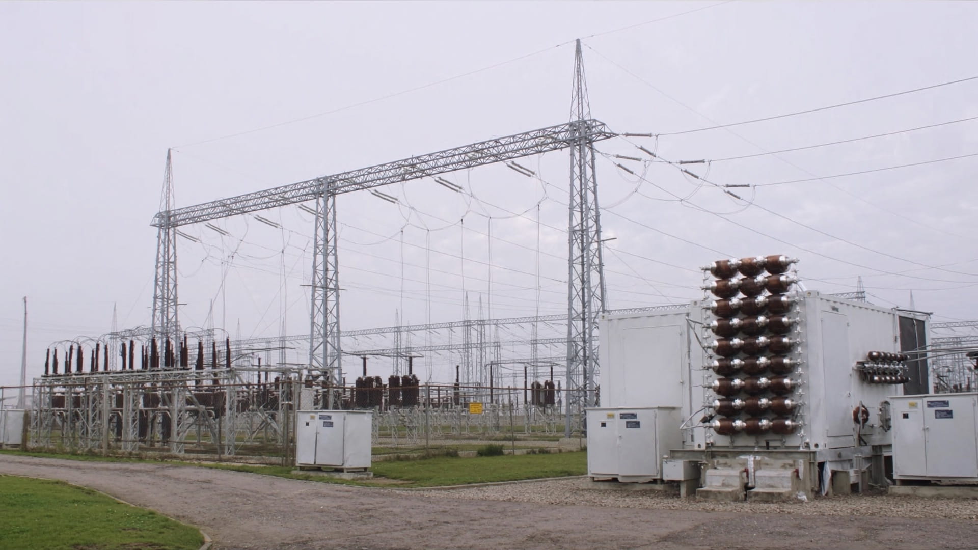
Renewable Energy and Drives reports that a STATCOM responds in about 1 to 2 ms, while an SVC typically needs 20 to 40 ms. This speed comes from the high switching frequency of the power semiconductors inside the converter.
Main Building Blocks of a STATCOM
Each converter valve is built from IGBT devices that can be switched on and off at will. This is the key difference from an SVC, whose thyristors can only be turned on and must wait for a current zero to turn off.
Large units now use a modular multilevel converter, where many small submodules stack up to form a near sinusoidal voltage. Siemens Energy describes its Kusenhorst SVC PLUS unit as rated for 300 MVAr in both directions, built from 4.5 kV power modules.
The DC capacitor of the converter does not need any external energy source in steady state. The converter draws only a small active current from the grid to cover its own losses and keep the capacitor charged.
How the STATCOM Controls Reactive Power
V = bus line voltage, kV
E = converter line voltage, kV
X = coupling reactance per phase, Ω
Q = 3 phase reactive power, MVAr
Example 1:
V = 33 kV, E = 34.5 kV, X = 5 Ω
Q = 33 × 1.5 ÷ 5
Q = 9.90 MVAr, capacitive mode
When E is larger than V, the current through the reactor leads the bus voltage, and the compensator supplies reactive power to the grid like a capacitor. When E is smaller than V, the current lags, and the device absorbs reactive power like a reactor.
Textbooks often write the same relation as Q = V(V minus E) ÷ X, measured as power flowing into the device. In that form a positive result means absorption, so always check which direction the author treats as positive before comparing numbers.
Before entering values in study software, confirm whether it reports reactive power as delivered to the grid or absorbed by the device. Mixing the two conventions is the most common error in STATCOM studies.
A small phase shift between E and V is also held on purpose. It lets a little active power flow into the converter to cover switching losses and hold the DC capacitor voltage at its set point.
Converter voltage E is higher than bus voltage V, so reactive power flows into the grid and raises the voltage.
Converter voltage E is lower than bus voltage V, so reactive power is absorbed and the voltage is pulled down.
E equals V, so no reactive current flows and the unit stays on standby.
Inductive mode is useful at night on long lightly loaded lines, where the Ferranti effect raises the receiving end voltage. Capacitive mode is used during heavy load, faults and voltage dips.
Reactive Power Exchange Calculator
Now try E = 32 kV with the same bus voltage and reactance. The result is minus 6.60 MVAr, which means the unit absorbs 6.60 MVAr in inductive mode.
The same calculation can be done in per unit, which is often easier for studies, as explained in per unit system. A small change in E gives a large change in Q, because X is kept deliberately small.
Low Voltage Behaviour of STATCOM and SVC
PSMA Consulting explains that a STATCOM can deliver its full output current even when system voltage falls to about 0.2 per unit. Its reactive output therefore falls only in proportion to voltage, while an SVC output falls with the square of voltage.
This matters most during faults and dips, exactly when the grid needs support. The behaviour of such events is covered in voltage sag, swell and flicker.
When comparing quotes, compare the reactive power available at 0.9 and 0.5 per unit voltage, not only the nameplate rating. A smaller converter based unit can often match a larger SVC during a dip.
STATCOM vs SVC Comparison
| Feature | STATCOM | SVC (TCR plus TSC) |
|---|---|---|
| Switching device | IGBT, turn off capable | Thyristor, line commutated |
| Response time | About 1 to 2 ms | About 20 to 40 ms |
| Output at low voltage | Proportional to V | Proportional to V squared |
| Harmonics | Low with multilevel converters | TCR needs harmonic filters |
| Footprint | Smaller, no large capacitor banks | Larger, with banks and reactors |
| Losses | Higher | Lower |
An SVC combines a thyristor controlled reactor with thyristor switched capacitors, and it varies an impedance. A STATCOM instead acts as a controlled current source, so its output does not depend on bank sizes.
The thyristor controlled reactor of an SVC produces low order harmonics that need tuned filters, as covered in harmonic distortion and THD. Multilevel STATCOM designs produce very little distortion and can even run as an active harmonic filter.
5 Key Advantages of a STATCOM
PSMA Consulting also notes that for the same stability margin the converter rating can be lower than that of an SVC. The main drawback is that total losses are higher, because IGBT switching produces more heat than thyristors.
A STATCOM with an energy storage device on its DC side can also exchange active power for short periods. Such hybrid designs are used for fast frequency support in some modern grids.
Where STATCOM Units Are Used
Grid codes, including the CEA connectivity standards in India, ask wind and solar plants to supply dynamic reactive power, typically across a 0.95 lagging to 0.95 leading power factor range. A plant STATCOM covers this range and also supports voltage during low voltage ride through.
In an arc furnace plant, the compensator reacts within one cycle to the rapidly changing reactive demand of the arc. This fast response is what makes it more effective against flicker than slower static equipment such as an APFC panel.
A D STATCOM is the distribution level version, usually rated from a few hundred kVAr to a few MVAr. It replaces or supplements fixed capacitor banks where the load changes quickly, and it is often placed on a radial distribution feeder with weak voltage.
Myths About STATCOM Technology
- Very fast and continuous control of reactive power.
- Strong support at low voltage.
- Compact layout, useful in space limited substations.
- Low harmonic output with multilevel converters.
- Higher cost per MVAr than an SVC.
- Higher losses from IGBT switching.
- Short time overload capacity is limited.
- Needs careful control tuning and cooling.
Sizing and Selection Checklist
- Run load flow and dynamic studies to find the MVAr range needed.
- Check grid code limits for reactive power, voltage and ride through.
- Decide whether a hybrid with switched capacitors can reduce cost.
- Specify response time, overload rating and harmonic limits.
- Confirm the transformer and coupling reactance values.
- Plan cooling, auxiliary supply and redundancy.
- Agree commissioning tests with the grid operator.
The required range usually comes from a load flow analysis that checks voltage at maximum and minimum load, and during outages. Combine the results with power factor correction needs, so that fixed steps take the slow part and the STATCOM handles the fast part.
Siemens Energy STATCOM Factsheet (PDF)
Video: How the STATCOM Beats the SVC
STATCOM FAQ
A STATCOM is a power electronic device that injects or absorbs reactive power to control grid voltage. It uses a voltage source converter connected to the bus through a small reactance.
By raising or lowering its own AC voltage, it pushes reactive current into the grid or draws it out. It works like a synchronous condenser but has no rotating parts.
When the converter voltage is set higher than the bus voltage, the unit supplies reactive power and acts like a capacitor. When it is set lower, the unit absorbs reactive power and acts like a reactor.
The change is made by the controller in a few milliseconds without any mechanical switching. The output can therefore move smoothly through zero from one mode to the other.
A STATCOM uses IGBT devices that can be turned on and off many times per cycle. An SVC uses thyristors that only turn off at a current zero, which slows its response.
Renewable Energy and Drives quotes about 1 to 2 ms for a STATCOM against 20 to 40 ms for an SVC. This speed is valuable during faults, dips and flicker.
PSMA Consulting explains that a STATCOM can supply full current down to about 0.2 per unit voltage. Its reactive power therefore falls only in direct proportion to voltage.
An SVC behaves like a fixed admittance, so its output falls with the square of voltage. This gives the converter based design a clear advantage during deep voltage dips, when voltage support matters most.
A D STATCOM is a smaller STATCOM installed in distribution networks, usually at medium or low voltage. It is typically rated from a few hundred kVAr to a few MVAr for industrial and utility feeders.
It corrects voltage fluctuation, power factor and flicker close to the load it serves. Many units can also filter harmonics at the same time, which saves a separate filter.
No, a normal STATCOM needs only a DC capacitor on the converter side. The capacitor is kept charged by a small active current drawn from the grid to cover losses.
Some designs add batteries or supercapacitors so that they can exchange active power as well. These hybrid systems are used for fast frequency support and short term power smoothing.
The main drawbacks are higher cost per MVAr and higher losses than an SVC. PSMA Consulting attributes the extra losses to the switching of the IGBT devices.
Its short time overload capacity is also limited by the semiconductor ratings and cooling. Many projects therefore combine the converter with mechanically switched capacitors to reduce the overall cost.
Related Articles
- Active, Reactive and Apparent Power
- Power Factor Correction Explained
- Voltage Sag, Swell and Flicker Explained
- Active Harmonic Filter Working and Sizing
- Capacitor Bank Sizing for Power Factor Correction
External References
- Stable Voltage for Future Proof Networks, STATCOM Factsheet, Siemens Energy
- STATCOM vs SVC: Choosing Dynamic Reactive Support, Renewable Energy and Drives
- Static Synchronous Compensator, Wikipedia
What We Learn Today
- A STATCOM supplies reactive power when its converter voltage is higher than the bus voltage, and absorbs it when the converter voltage is lower.
- Compared with an SVC, it responds within milliseconds and keeps full current at low voltage, but it costs more and has higher losses.
- Wind and solar farms, arc furnaces, transmission nodes and distribution feeders use it for fast voltage support and flicker control.