
The way feeders are arranged decides how many people lose power when one cable or breaker fails.
A power distribution system layout describes how feeders connect substations to loads. Radial systems are simple and cheap, while ring and interconnected systems keep power flowing when a section fails.
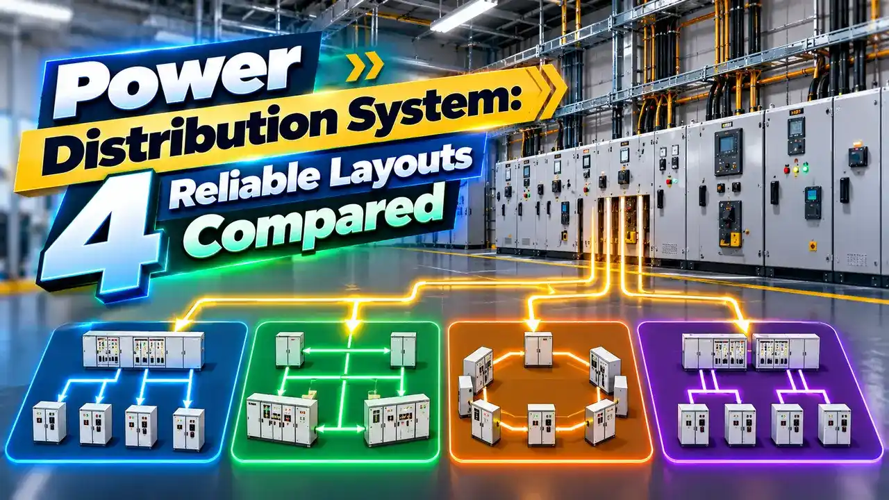
What Is a Power Distribution System Layout?
A power distribution system layout is the arrangement of feeders, switchgear and transformers that carries power from the supply point to every load. It is shown clearly in the plant single line diagram.
The chosen layout affects cost, reliability, voltage regulation, fault levels and how easily sections can be isolated for maintenance. There is no single best choice for every site.

Utilities use these layouts on their networks, and large plants copy the same ideas inside their own boundaries. The principles are identical at 11 kV, 33 kV and 415 V.
Reliability requirements usually drive the choice. A continuous process plant cannot accept the outage that a small workshop might tolerate.
4 Reliable Distribution Layouts
Electricaleasy notes that radial systems are simplest but lose supply to all downstream loads when a feeder fails. Ring main systems give continuity through an alternate route.
Ring main units, covered in ring main unit maintenance, are the compact switchgear that make ring layouts practical at 11 kV.
Industrial Plant Schemes
One transformer and one main board feed all loads.
Each transformer can be fed from either of two HV feeders.
Double ended board with two transformers and a bus tie breaker.
Several transformers in parallel feed one LV bus.
Secondary selective, often called a double ended substation, is the favourite for process industries. If one transformer fails, the bus tie closes and the other transformer carries essential load.
Automatic changeover between sources uses the same logic as an automatic transfer switch, with interlocks to prevent paralleling when not allowed.
Power Distribution System Comparison
| Layout | Reliability | Cost | Protection Complexity | Typical Use |
|---|---|---|---|---|
| Radial | Low | Lowest | Simple | Small loads |
| Parallel feeder | Medium | High | Moderate | Heavy load areas |
| Ring main | High | Medium | Moderate | Urban networks |
| Interconnected | Very high | Highest | Complex | City grids |
| Secondary selective | High | Medium to high | Moderate | Process plants |
More sources and ties mean higher fault levels and more complex protection. Plan grading carefully using breaker coordination studies.
Before finalizing, run a load flow analysis to check voltages and loading under normal and contingency cases.
Voltage Drop by Layout Formula
Uniform load, radial: Vd = I × R × L ÷ 2
Uniform load, fed from both ends: Vd = I × R × L ÷ 8
Worked example per conductor:
I = 200 A, R = 0.2 Ω per km, L = 1 km
End load: 200 × 0.2 × 1 = 40 V
Uniform radial: 40 ÷ 2 = 20 V
Uniform, fed from both ends: 40 ÷ 8 = 5 V
Feeding a distributed load from both ends cuts the maximum voltage drop dramatically. That is one practical advantage of ring and interconnected layouts besides reliability.
These are simplified per conductor values for resistive drop. Full calculations follow the method in voltage drop explained.
How Faults Affect Each Layout
In a normally open ring, one switch in the loop stays open. After a fault, operators isolate the faulty section and close the open point to restore supply.
Closed rings restore supply automatically but need directional or unit protection. The choice depends on budget and on how quickly supply must return.
Where Each Layout Fits
Data centres take redundancy furthest, as shown in Tier IV power architecture.
For most plants, secondary selective LV boards fed by a primary ring give an excellent balance of cost and reliability.
Distribution Voltage Drop Calculator
Multiply by the correct factor for single phase or three phase line drop. The comparison between layouts stays the same.
- Lowest cost.
- Simple protection.
- Easy to understand and operate.
- Good for small, non critical loads.
- Single fault interrupts downstream loads.
- Poorer voltage at feeder ends.
- No backup during maintenance.
- Limited expansion flexibility.
Electrical Installation Guide Reference
Radial and Ring Main Distribution Video
Power Distribution System FAQ
Related Articles
- Ring Main Unit Maintenance
- Single Line Diagram Symbols
- Automatic Transfer Switch Explained
- Load Flow Analysis for Industrial Plants
- Circuit Breaker Coordination
External References
- Distribution System Topologies, electricaleasy
- Radial and Ring Main Systems, Electrical4U
- Electrical Installation Guide, Schneider Electric
- Electric Power Distribution, Wikipedia
What We Learn Today
- Radial is cheap and simple, ring and interconnected layouts add continuity.
- Secondary selective double ended boards suit critical process plants.
- Feeding loads from both ends sharply reduces voltage drop.