
Connect a tiny load and almost no current flows, connect a huge load and almost no voltage appears across it. Somewhere in between lies one load value that pulls the most power from the source, and a single derivative tells us exactly where.
Every real source has some internal resistance, and that resistance decides how much power it can deliver to a load. This theorem finds the best load, explains why efficiency is only half at that point and shows where engineers use it.
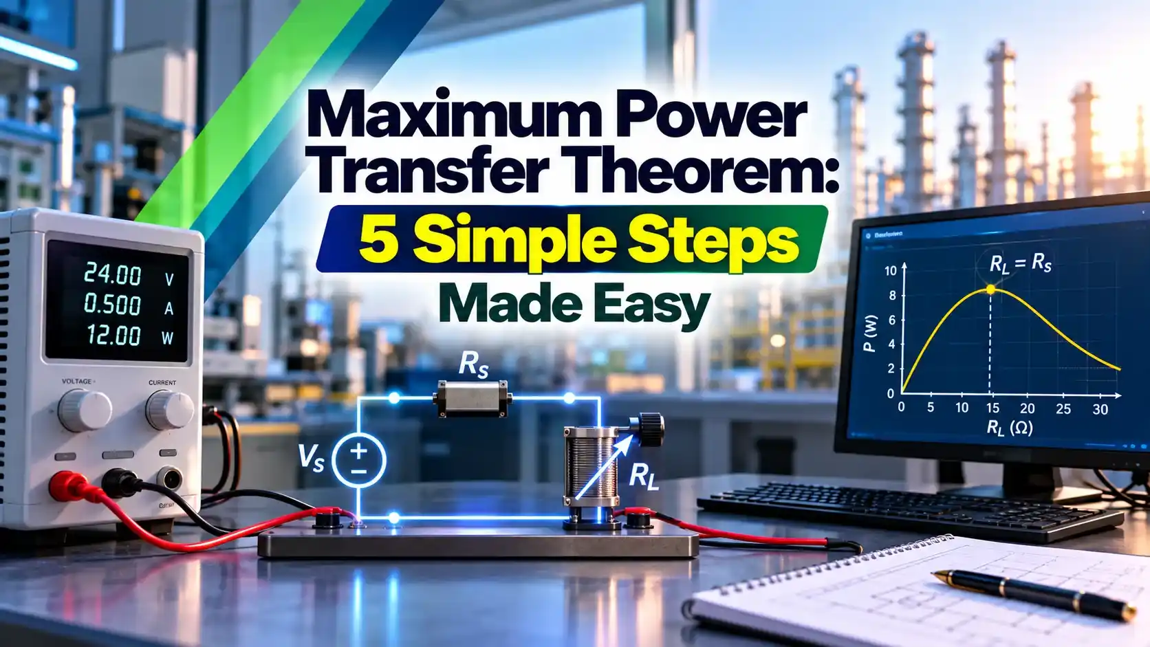
What Is the Maximum Power Transfer Theorem?
The maximum power transfer theorem states that a linear source delivers the greatest possible power to a load when the load resistance equals the internal or Thevenin resistance of the source. Any complex network can first be reduced to one voltage and one series resistance using Thevenin theorem.
The maximum power transfer theorem is often called Jacobi law after Moritz von Jacobi, who described it in the early days of electric motors. It applies to DC circuits directly and to AC circuits with a small change for reactance.
The curve rises steeply for small loads, peaks when the load matches the source and then falls slowly for larger loads. That peak is the operating point the theorem predicts.
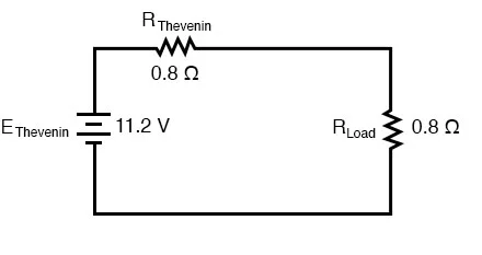
The load current in the simple series circuit follows Ohm law, and the two resistances add like any series circuit. That is all the circuit theory needed for the proof.
At maximum power transfer the load voltage is exactly half of the open circuit voltage. The other half is dropped across the internal resistance of the source.
Proof Using Calculus
Take a source voltage Vth with internal resistance Rth feeding a load RL. The current is Vth ÷ (Rth + RL), and power in the load is current squared times RL.
P = I² × RL = Vth² × RL ÷ (Rth + RL)²
Set dP/dRL = 0:
Vth² × [(Rth + RL)² minus 2 × RL × (Rth + RL)] ÷ (Rth + RL)⁴ = 0
(Rth + RL) minus 2 × RL = 0
RL = Rth
Substituting back:
Pmax = Vth² ÷ (4 × Rth)
The second derivative is negative at this point, so the result is a true maximum and not a minimum. Prof Fiore of Mohawk Valley Community College shows the same proof using the quotient, product and chain rules, which all give RL = Rth.
When the source is easier to describe as a current source, the same answer comes from Norton theorem. The Norton resistance equals the Thevenin resistance, so the matched load value does not change.
Why Efficiency Is Only 50 Percent
Efficiency is load power divided by total power, and the same current flows through both resistances. So efficiency is simply RL ÷ (Rth + RL), which equals exactly 0.5 when RL = Rth.
Triad Magnetics puts it plainly: at matched impedance, the maximum power that can be transferred is 50 percent. Half of the energy drawn from the source heats the source itself.
| RL ÷ Rth | Efficiency | Load Power ÷ Pmax |
|---|---|---|
| 0.5 | 33.3 % | 0.889 |
| 1 | 50.0 % | 1.000 |
| 2 | 66.7 % | 0.889 |
| 4 | 80.0 % | 0.640 |
| 10 | 90.9 % | 0.331 |
| 100 | 99.0 % | 0.039 |
The table shows the trade off clearly. Raising the load well above the source resistance gives high efficiency but much less power, while matching gives the most power at poor efficiency.
Remember the ratio 4k ÷ (1 + k)² for load power as a fraction of the maximum, where k is RL ÷ Rth. It lets you estimate mismatch loss in your head during exams and lab work.
5 Simple Steps to Solve MPT Problems
Finding Vth usually needs Kirchhoff voltage law or Kirchhoff current law. Circuits with several sources can be simplified first with the superposition theorem.
When finding Rth, replace voltage sources by short circuits and current sources by open circuits. Dependent sources must stay in the circuit, and then a test source method is used instead.
Worked Example With a Thevenin Equivalent
Consider a 24 V source with a 6 Ω series resistor, a 12 Ω resistor across the output and a further 2 Ω in series with the load terminal. We want the load that takes maximum power and the value of that power.
Vth = 24 × 12 ÷ (6 + 12) = 16 V
Step 2, Thevenin resistance with source shorted:
Rth = (6 × 12 ÷ 18) + 2 = 4 + 2 = 6 Ω
Step 3, matched load:
RL = 6 Ω
Step 4, maximum power:
Pmax = 16² ÷ (4 × 6) = 256 ÷ 24 = 10.67 W
At this point the load voltage is 8 V and the current is 1.33 A. The 24 V source actually supplies more than 10.67 W, because the internal network also dissipates power.
Understanding resistance values and their tolerance is covered in what is resistance. A 6 Ω load built from standard parts might be 5.6 Ω, which still gives more than 99 percent of Pmax.
AC Version and Conjugate Matching
In AC circuits the source has an impedance Zth = Rth + jXth, as explained in what is impedance. Maximum average power flows when the load is the complex conjugate, ZL = Rth minus jXth.
The conjugate reactance cancels the source reactance, leaving a purely resistive loop, which is the idea behind resonance in impedance and reactance in AC circuits. The maximum power is then Vth² ÷ (4 × Rth), with Vth as an rms value.
Conjugate load:
ZL = 3 minus j4 Ω
Pmax = 10² ÷ (4 × 3) = 8.33 W
If only a resistor is allowed, RL = |Zth| = 5 Ω
I = 10 ÷ |8 + j4| = 10 ÷ 8.94 = 1.118 A
P = 1.118² × 5 = 6.25 W
The pure resistor gets only 6.25 W against 8.33 W with the conjugate load. Only the real part of the load absorbs average power, which links to active, reactive and apparent power.
Load resistance equals source resistance.
Load impedance is the conjugate of the source impedance.
Resistive load equals the magnitude of source impedance.
Maximum Power Transfer Theorem Calculator
Vth = 12 V, Rth = 4 Ω, RL = 6 Ω
I = 12 ÷ (4 + 6) = 1.2 A
P = 1.2² × 6 = 8.64 W
Efficiency = 6 ÷ 10 = 60.0 %
Pmax = 12² ÷ (4 × 4) = 9.00 W at RL = 4 Ω
Try RL values of 2, 4, 8 and 40 Ω to see the power curve and the efficiency climb. Moving from 4 Ω to 6 Ω loses only 4 percent of power but gains 10 points of efficiency.
Applications of Impedance Matching
Triad Magnetics gives a tube amplifier example: 128 W into an 8 Ω speaker needs 32 V at 4 A, while the tube stage works at about 384 V and 0.333 A. A transformer with a 12 to 1 voltage ratio gives a 144 to 1 impedance ratio, matching the 1152 Ω stage to the speaker.
In RF work, a mismatch reflects part of the power back toward the transmitter, and the loss is usually expressed in decibels. The notation is explained in decibel in electronics, dB and dBm.
A solar panel is not a linear source, but its best operating point still behaves like a matched load at each light level. MPPT controllers use a DC converter, like the one in boost converter working principle, to present that optimum load continuously.
Most RF cables, connectors and test instruments use 50 Ω as a standard impedance. Cable television and many video systems use 75 Ω instead, because it gives lower loss in coaxial cable.
Why Power Systems Avoid Matched Loads
A power grid is designed for efficiency and stable voltage, not for maximum power from a fixed source. If a generator were matched to its load, half of all generated energy would be lost inside the machine and the terminal voltage would fall to half.
Real generators and transformers have internal impedance far smaller than the load impedance, so efficiency stays well above 95 percent. Utilities also improve power factor to reduce current rather than to match impedance.
The maximum power transfer theorem only answers one question: which load draws most power from a given source. If you are free to design the source, the best choice is the lowest possible internal resistance, which raises both power and efficiency.
In the lab, measure Rth by recording open circuit voltage, then adding a known load and measuring the new voltage. Rth equals RL × (Voc minus VL) ÷ VL, with no need to open the circuit.
Common Mistakes Students Make
- Leaving the load connected while finding Vth.
- Forgetting to short voltage sources when finding Rth.
- Removing dependent sources instead of using a test source.
- Using peak voltage instead of rms in AC power formulas.
- Matching RL to the magnitude of Zth when a conjugate load is possible.
- Quoting 100 percent efficiency at maximum power.
Most exam errors come from a wrong Rth rather than from the power formula. Check Rth twice, once by source removal and once by open circuit voltage divided by short circuit current.
- Gives the most power from weak sources.
- Simple rule once Thevenin form is known.
- Basis of RF and audio matching.
- Guides MPPT and sensor interface design.
- Efficiency only 50 percent at the matched point.
- Valid for linear circuits only.
- Source must be fixed, only the load varies.
- Unsuitable for power distribution systems.
DC Proof Notes PDF
Thevenin and Matching Video
Maximum Power Transfer Theorem FAQ
It states that maximum power reaches the load when load resistance equals the Thevenin resistance of the source network. For AC circuits, the load impedance must be the complex conjugate of the source impedance.
The source is assumed fixed while only the load is allowed to change. Under these conditions the load power equals Vth squared divided by four times Rth.
Efficiency is exactly 50 percent because the same current flows through two equal resistances. Half of the power is lost as heat inside the source and only half reaches the load.
Higher efficiency needs a load resistance much larger than the source resistance. The price is lower power delivered to that load, as the efficiency table shows.
Write load power as Vth squared times RL divided by the square of the total loop resistance. Differentiate this expression with respect to RL and set the result equal to zero.
The equation then simplifies neatly to RL equals Rth. A negative second derivative at that point confirms that it is a true maximum and not a minimum.
It means choosing a load impedance whose reactance is equal in size and opposite in sign to the source reactance. The load resistance is also made equal to the source resistance.
The two reactances cancel, so the loop becomes purely resistive at that frequency. This gives the largest possible average power in RF, antenna and tuned amplifier circuits.
A matched generator would waste half of its output as heat in its own windings and cables. Its terminal voltage would also drop to half of the open circuit value, which no consumer could accept.
Power systems therefore keep source impedance very small compared with the load. This gives efficiency well above 95 percent and good voltage regulation.
A solar panel has one best operating point on its current and voltage curve at each light level and temperature. An MPPT controller keeps adjusting the effective load so that the panel stays at that point.
The idea closely mirrors matching a load to a source. The panel is nonlinear, so the controller searches for the peak instead of using one fixed resistance.
The classic result assumes a linear source that has a valid Thevenin equivalent. Diodes, transistors and solar cells are nonlinear, so the simple formula is only an approximation for them.
For such devices, engineers linearise the circuit around a chosen operating point. They may also search for the peak power point numerically, exactly as MPPT controllers do.
Related Articles
- Thevenin Theorem Made Simple
- Norton Theorem Explained With Solved Examples
- Superposition Theorem Explained
- What Is Impedance
- Active, Reactive and Apparent Power
External References
- DC Maximum Power Transfer Theorem Proof, Mohawk Valley Community College
- Understanding the Maximum Power Theorem, Triad Magnetics
- Maximum Power Transfer Theorem, Wikipedia
What We Learn Today
- The maximum power transfer theorem says load power peaks when load resistance equals the Thevenin resistance, giving Pmax equal to Vth squared over 4Rth.
- Efficiency at the matched point is only 50 percent, so power grids use loads far larger than source impedance to keep losses low.
- AC circuits need conjugate matching, and the same idea drives audio transformers, 50 Ω RF systems and solar MPPT controllers.