
Any tangle of resistors and sources, no matter how complicated, behaves exactly like one voltage source and one resistor as far as a single load is concerned. Here is exactly how the theorem finds that equivalent, with a real circuit diagram and a live calculator you can try right now.
What Is Thevenins Theorem?
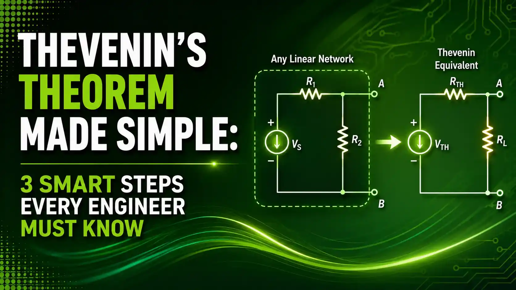
Thevenin's Theorem states that any linear circuit containing multiple voltage sources and resistors can be replaced by a single equivalent voltage source in series with a single equivalent resistance, as seen from two output terminals.
That means no matter how tangled the internal wiring gets, from the outside looking in, the whole network behaves exactly like one battery and one resistor. This makes analyzing how a circuit responds to different loads dramatically simpler.
The theorem builds directly on Kirchhoff's Current Law and Kirchhoff's Voltage Law, using both to derive its equivalent voltage and resistance values.
This guide covers the three smart steps behind the theorem, from removing the load to reconnecting it, with a real worked example you can follow along with.

How the Theorem Simplifies a Circuit
Every application of the theorem follows the same basic four-stage process.
Remove the Load
Disconnect the specific resistor or component whose voltage or current you want to find.
Find the Open-Circuit Voltage
Calculate the voltage across the open terminals left behind, this becomes the Thevenin voltage.
Find the Equivalent Resistance
Short all voltage sources, open all current sources, and calculate the resistance looking back into the network.
Reconnect and Analyze
Rebuild the circuit as a single source and resistor, then reconnect the load to solve easily.
3 Smart Steps to Master Thevenin's Theorem
These three ideas explain why the theorem works and how to apply it correctly every time.
Any Linear Network Reduces to Just Two Numbers
Regardless of how many resistors and sources sit inside the network, the entire thing collapses down to a single Thevenin voltage and a single Thevenin resistance, as seen from the two terminals of interest.
Sources Must Be Deactivated Correctly to Find Rth
Finding the Thevenin resistance requires replacing every independent voltage source with a short circuit and every independent current source with an open circuit, then measuring the resistance from the terminals.
The Equivalent Only Needs to Match at the Terminals
Thevenin's equivalent circuit does not reproduce what happens inside the original network. It only needs to behave identically from the perspective of whatever load gets connected to those two terminals.
A Real Worked Example
Consider a classic Thevenin example circuit with a 20V source, a 10-ohm resistor, and a 20-ohm resistor, feeding a 40-ohm load resistor.
What is happening: Removing the 40-ohm load and shorting the source leaves 10 ohms and 20 ohms in parallel, giving an equivalent resistance of 6.67 ohms.
A real example: With the load removed, the open-circuit voltage across the terminals works out to 13.33V, using simple voltage divider reasoning across the two remaining resistors.
Why it works: Once you have both Vth and Rth, reconnecting the 40-ohm load to this simple two-component equivalent circuit gives the exact same current and voltage the original, more complex circuit would have produced.
This becomes especially valuable when you need to test several different load resistor values against the same source network. Rather than re-solving the entire original circuit each time, you calculate Vth and Rth once, then simply swap in each new load against that same simple equivalent.
Consider a design team evaluating five candidate load resistances for a new sensor interface. Solving the full original network from scratch for each candidate would mean repeating the same tedious circuit reduction five separate times. Reducing the source network to its Thevenin equivalent just once turns each of those five evaluations into a single, quick Ohm's law calculation instead.
Formula for Load Current Using Thevenin Values
Once Vth and Rth are known, finding the load current reduces to one simple Ohm's law step.
Load current: IL = Vth / (Rth + RL)
Worked example: Vth = 13.33V, Rth = 6.67Ω, RL = 40Ω
IL = 13.33 / (6.67 + 40) = 0.286A
Try It: Thevenin Equivalent Calculator
Enter a source voltage and two series/parallel resistor values to find Vth and Rth, then see the resulting load current.
Thevenin's Theorem vs Other Analysis Methods
| Method | Best For | Practical Note |
|---|---|---|
| Thevenin's Theorem | Testing multiple load values against one source network | Reduces to a single voltage source and resistor |
| Norton's Theorem | Circuits more naturally analyzed with current sources | Reduces to a single current source and parallel resistor |
| Mesh Analysis | Circuits with many independent loops | Applies KVL directly to each loop |
| Nodal Analysis | Circuits with many nodes but few loops | Applies KCL directly to each node |
Applications of the Theorem
Battery and Power Supply Modeling
Real batteries are often modeled as a Thevenin voltage source with internal resistance.
Signal Source Modeling
Sensor and transducer outputs are frequently represented using their Thevenin equivalent.
Maximum Power Transfer Analysis
Finding the load resistance for maximum power transfer requires the Thevenin resistance.
Load Variation Studies
Engineers swap different load values against one fixed Thevenin equivalent quickly.
Amplifier Output Modeling
An amplifier's output stage is commonly reduced to a Thevenin source for load analysis.
Circuit Simulation Preprocessing
Simulators sometimes reduce a subnetwork to its Thevenin equivalent to speed up analysis.
What ties all six of these roles together is the same underlying motivation: replacing a genuinely complicated internal network with the simplest possible external behavior. Whether that external behavior feeds a load resistor, a sensor interface, or another stage of amplification, the two-number summary of Vth and Rth captures everything an outside observer actually needs to know.
Advantages and Limitations of the Theorem
Why Thevenin's Theorem Is So Useful
Limitations to Keep in Mind
Download Thevenin References
These two academic references go deeper into the theorem and Norton equivalent circuits.
6.200 Notes: Thevenin-Helmholtz and Mayer-Norton Theorems
Official MIT lecture notes deriving Thevenin and Norton equivalents
ECE 10A Lecture 16: Thevenin and Norton Equivalent Circuits
UC Santa Barbara lecture notes with additional worked examples
Both references walk through the same core derivation from slightly different angles, which is worth reading if the first explanation does not fully click. Circuit theory concepts like this one often take seeing the same idea presented twice, in two different instructors' words, before the underlying logic truly settles in.
Watch: Thevenin's Theorem Explained
This video walks through applying the theorem to find load current in a real circuit.
FAQs on Thevenin's Theorem
External References
- MIT 6.200, Thevenin-Helmholtz and Mayer-Norton Theorems
- UC Santa Barbara, ECE 10A Lecture 16, Thevenin and Norton Equivalent Circuits
- Electronics Tutorials, Thevenin's Theorem Tutorial for DC Circuits
- YouTube, Thevenin's Theorem, Circuit Analysis
What we learn today
- Thevenin's Theorem reduces any linear network to a single voltage source in series with a single resistance, as seen from two terminals.
- The three-step process is: remove the load, find Vth as the open-circuit voltage, find Rth by deactivating all sources.
- The equivalent circuit only needs to match the original at the terminals, not reproduce its internal behavior.
- Thevenin's Theorem builds directly on Kirchhoff's Current Law and Kirchhoff's Voltage Law.
- The theorem is especially valuable for testing multiple load values quickly against the same source network.