
Light covers about 30 centimetres in a single nanosecond, so timing its trip to a target and back reveals the distance with remarkable precision. Tiny laser modules now do this thousands of times per second at very low cost.
Robots, smartphones and automated vehicles all need to know how far away things are. Optical ranging measures the travel time of light, giving fast, compact and non contact distance data.
What Is a Time of Flight Sensor?
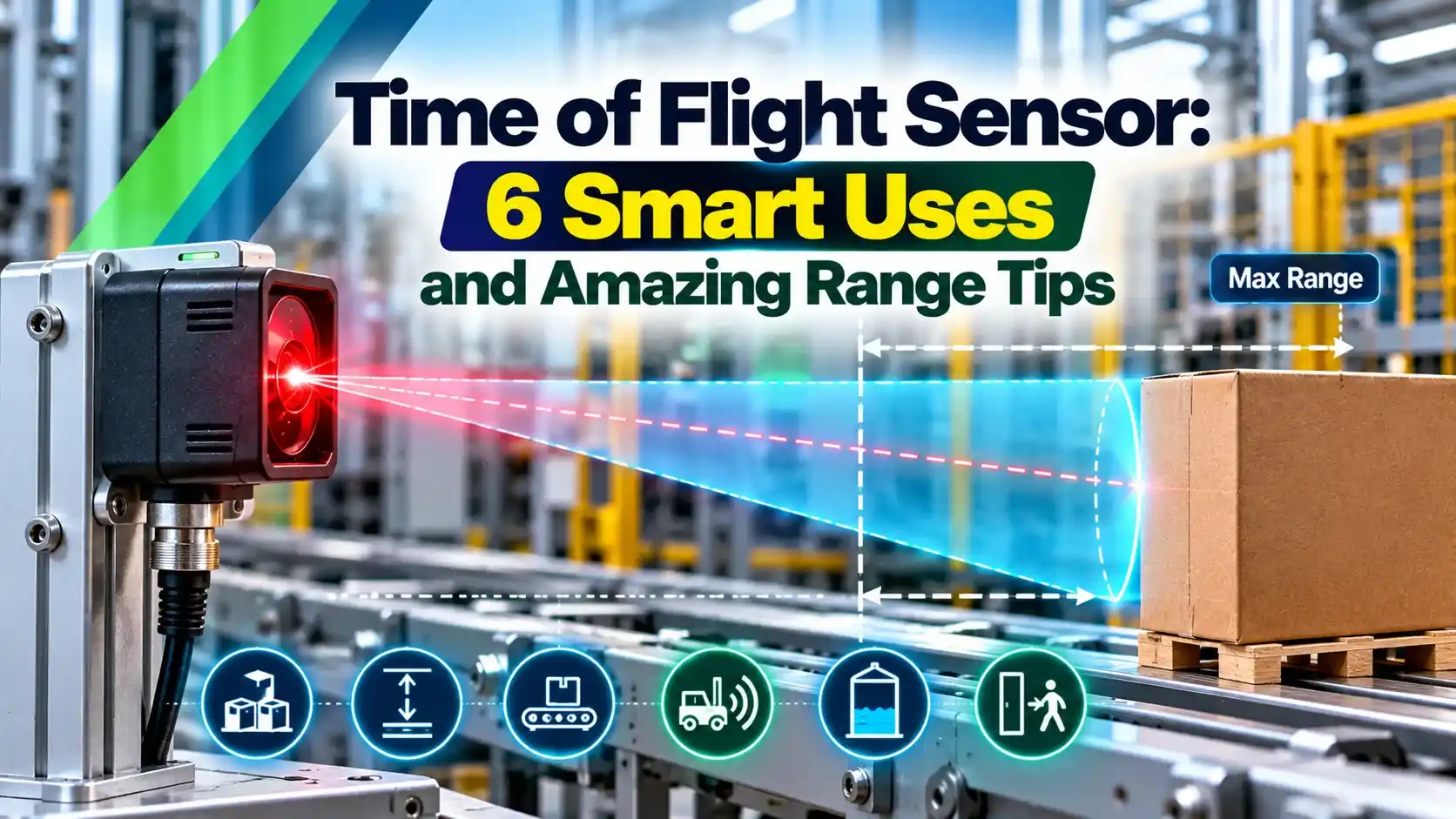
A time of flight sensor is an optical distance sensor that emits light, usually infrared, and measures how long the light takes to reach a target and return. Since the speed of light is known, the round trip time converts directly into distance, much like the echo principle in the HC SR04 ultrasonic sensor.
Modern modules combine a 940 nm vertical cavity laser, a single photon detector array and timing logic in one small package. STMicroelectronics VL53L0X and VL53L1X parts are popular examples that talk to a host over I2C.
Unlike a simple photoelectric sensor that only reports presence, the ToF module reports an actual distance in millimetres. That makes it useful for measuring, not just detecting.
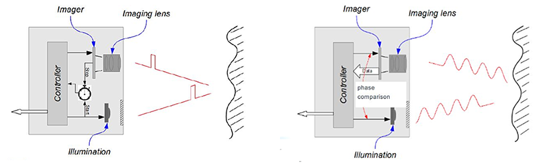
Direct and Indirect Measurement Methods
Sends short laser pulses and times each return with SPAD detectors and a time to digital converter.
Sends continuously modulated light and measures the phase shift of the returning wave.
Uses a SPAD array with several zones to give a coarse depth map.
A single photon avalanche diode, or SPAD, can detect individual photons, so direct ToF chips build a histogram of arrival times from many pulses. The histogram peak gives the round trip time even when the return signal is weak.
Indirect ToF cameras sample the returning light at four points of the modulation cycle, as Terabee explains, and calculate the phase from those samples. Each pixel of such a camera becomes its own tiny rangefinder, which is the basis of the 3D lidar sensors used in industry.
Resolving 1 mm of distance with direct timing needs about 6.7 picoseconds of time resolution. That is why ToF chips average many pulses instead of relying on one measurement.
How a Time of Flight Sensor Measures Distance
The raw photons are weak, so the chip repeats this cycle many times per reading and filters the results. A host microcontroller then reads the result, often using the bus described in SPI vs I2C.
Distance and Ambiguity Range Formulas
Phase method: d = c × φ ÷ (4π × f)
Maximum unambiguous range: R max = c ÷ (2 × f)
c = 299792458 m/s, t = round trip time, φ = phase shift in radians, f = modulation frequency
Example:
t = 20 ns, d = 299792458 × 0.00000002 ÷ 2 = 2.998 m
φ = 90 degrees = π ÷ 2 at f = 10 MHz, d = 3.747 m
R max at 10 MHz = 299792458 ÷ 20000000 = 14.99 m
The factor of two appears because light travels to the target and back. In the phase method, a full 360 degree shift corresponds to half the modulation wavelength, which is why the range repeats.
ToF Distance and Range Calculator
Lower modulation frequencies give a longer unambiguous range but coarser precision. Higher frequencies give finer precision but wrap around sooner.
Second Worked Example: Phase Wrap Around
Terabee gives a clear example: a 10 MHz wave completes one cycle over 30 m, so the maximum measurable distance is 15 m. A target at 22.5 m would be reported as 7.5 m, because the sensor cannot tell that an extra cycle has passed.
The fix is to measure with two modulation frequencies, which Terabee uses in its TeraRanger Evo. Only one distance fits both phase readings, which extends the usable range while keeping fine resolution.
When a reading suddenly jumps from far to near, suspect phase wrap around from a bright distant object. Limit the field of view or use a dual frequency mode.
ToF vs Ultrasonic vs IR Triangulation
| Feature | Optical ToF | Ultrasonic | IR Triangulation |
|---|---|---|---|
| Principle | Light travel time | Sound echo time | Spot position on a detector |
| Beam | Narrow, about 25 degrees or less | Wide cone | Narrow spot |
| Speed of signal | Light, 300000 km/s | Sound, about 343 m/s in air | Not time based |
| Temperature effect | Very small | Sound speed changes with air temperature | Small |
| Output | Linear distance | Linear distance | Nonlinear voltage |
| Weakness | Sunlight, dark or glass targets | Soft or angled targets, foam | Short range, colour |
Ultrasonic sensors, like those in ultrasonic level transmitters, cope well with dust and glass but have a wide beam. For long process ranges, industrial radar level transmitters and laser level transmitters use the same time of flight idea with more power.
These figures come from the ST VL53L1X datasheet, which also lists a 2.6 to 3.5 V supply and I2C at up to 400 kHz. The same datasheet shows range dropping to 73 cm in strong sunlight in long distance mode.
What Affects Accuracy
Ambient infrared light, especially sunlight, adds photons that raise the noise floor and shorten the range. Filters at 940 nm help, but outdoor range is always shorter than indoor range.
Target reflectance matters too, since a white card returns far more light than black rubber or dark cloth. Mirrors and glossy surfaces can send the beam away, while transparent objects may let it pass straight through.
Cover glass in front of the sensor reflects part of the emitted light back into the detector, a problem called crosstalk. ST provides offset and crosstalk calibration routines, and the cover must be tested in the final product.
Installing a Time of Flight Sensor
A longer timing budget averages more photons, reducing noise at the cost of update rate. General guidance on matching sensor, range and environment is in sensor selection criteria.
The VL53L1X laser is rated Class 1 under IEC 60825 1, so it is eye safe in normal use. Its 940 nm light is invisible, yet many phone cameras can see the faint glow.
6 Smart Uses of a Time of Flight Sensor
In factories, ToF modules often sit beside inductive proximity sensors and other industrial automation sensors to add real distance values. For presence only, a PIR sensor is cheaper, but it cannot measure how far a person is.
Depth cameras based on indirect ToF also support machine vision for quality inspection, measuring box sizes and fill heights. The receiver inside such systems is a fast photodiode, compared in photodiode vs phototransistor.
- Linear distance output in millimetres.
- Small, low power and low cost modules.
- Narrow beam compared with ultrasonic.
- Fast readings, up to tens per second.
- Range falls in bright sunlight.
- Dark, shiny or clear targets are difficult.
- Cover glass crosstalk needs calibration.
- Short range compared with industrial radar.
Time of Flight Sensor Selection Checklist
- Required range with margin for dark targets.
- Indoor or outdoor ambient light level.
- Field of view and single or multizone output.
- Update rate and timing budget.
- Supply voltage and I2C address conflicts.
- Cover window material and crosstalk calibration.
- Eye safety class and certification.
Several identical modules on one bus need unique addresses, usually set at start up by holding the others in shutdown with their XSHUT pins. Plan this in the wiring before the board is built.
Mount the sensor slightly recessed and black out the gap around the window. This one step removes most crosstalk and false short readings.
VL53L1X Datasheet PDF
VL53L0X Lidar Demonstration Video
Time of Flight Sensor FAQ
It is an optical sensor that emits infrared light and measures how long the light takes to return from a target. The round trip time is converted into distance using the speed of light.
Most compact modules use a 940 nm laser and SPAD detectors on one chip. They report distance in millimetres over I2C to a microcontroller.
For the direct method, distance equals the speed of light times the round trip time divided by two. A 20 ns round trip gives about 2.998 m.
For the phase method, distance equals c times the phase shift divided by 4π times the modulation frequency. A 90 degree shift at 10 MHz gives about 3.747 m.
It is the largest distance a phase based sensor can measure before the phase repeats. It equals the speed of light divided by twice the modulation frequency.
At 10 MHz it is about 15 m, so a target at 22.5 m wrongly reads 7.5 m. Dual frequency measurement, as used in the Terabee TeraRanger Evo, removes this error.
ST specifies up to 400 cm in the dark with a suitable white target. The range becomes much shorter in bright light, down to 73 cm in strong sunlight in long distance mode.
Target colour and surface also change the usable range. Always test with the real target material, mounting and lighting before finalising a design.
Optical ToF has a much narrower beam, a faster response and very small temperature error. It is ideal for compact robots, gesture sensing and short range detection on machines.
Ultrasonic sensors work better with clear glass, dusty air and bright sunlight. The better choice depends on the target material, the environment and the required range.
Part of the emitted light reflects from the inside of the window straight into the detector. This crosstalk makes the sensor read shorter distances or report false targets.
Use an IR transparent window with a small air gap and run the crosstalk calibration with the final cover fitted. ST provides dedicated routines for this in its driver software.
Modules such as the VL53L1X are rated Class 1 under IEC 60825 1, which is safe under normal use. The 940 nm light is invisible to the human eye.
Do not modify the optics or the laser drive current, since that can change the safety rating. Follow the datasheet guidance on cover windows, spacing and assembly.
Related Articles
- Ultrasonic Distance Sensor HC SR04
- Different Types of Photoelectric Sensors
- Laser Level Transmitter Working Principle
- 3D Lidar Sensors in Industrial Applications
- Sensor Selection Criteria
External References
- VL53L1X Datasheet, STMicroelectronics
- Introduction to Indirect ToF Sensing, Terabee
- Time of Flight Camera, Wikipedia
What We Learn Today
- A time of flight sensor times light travelling to a target and back, so distance equals the speed of light times time divided by two.
- Phase based sensors use d = c × φ ÷ (4π f), and their unambiguous range is c ÷ (2f), about 15 m at 10 MHz.
- Sunlight, dark or shiny targets and cover glass crosstalk limit accuracy, so calibration and careful mounting are essential in every design.