
Two wires and addresses, or four wires and raw speed, the choice shapes your board layout, pin count and firmware.
SPI and I2C are the two most common on board serial buses for sensors, memories, ADCs and displays. Both use a clock and a controller, but they differ in wiring, speed and how devices are selected.
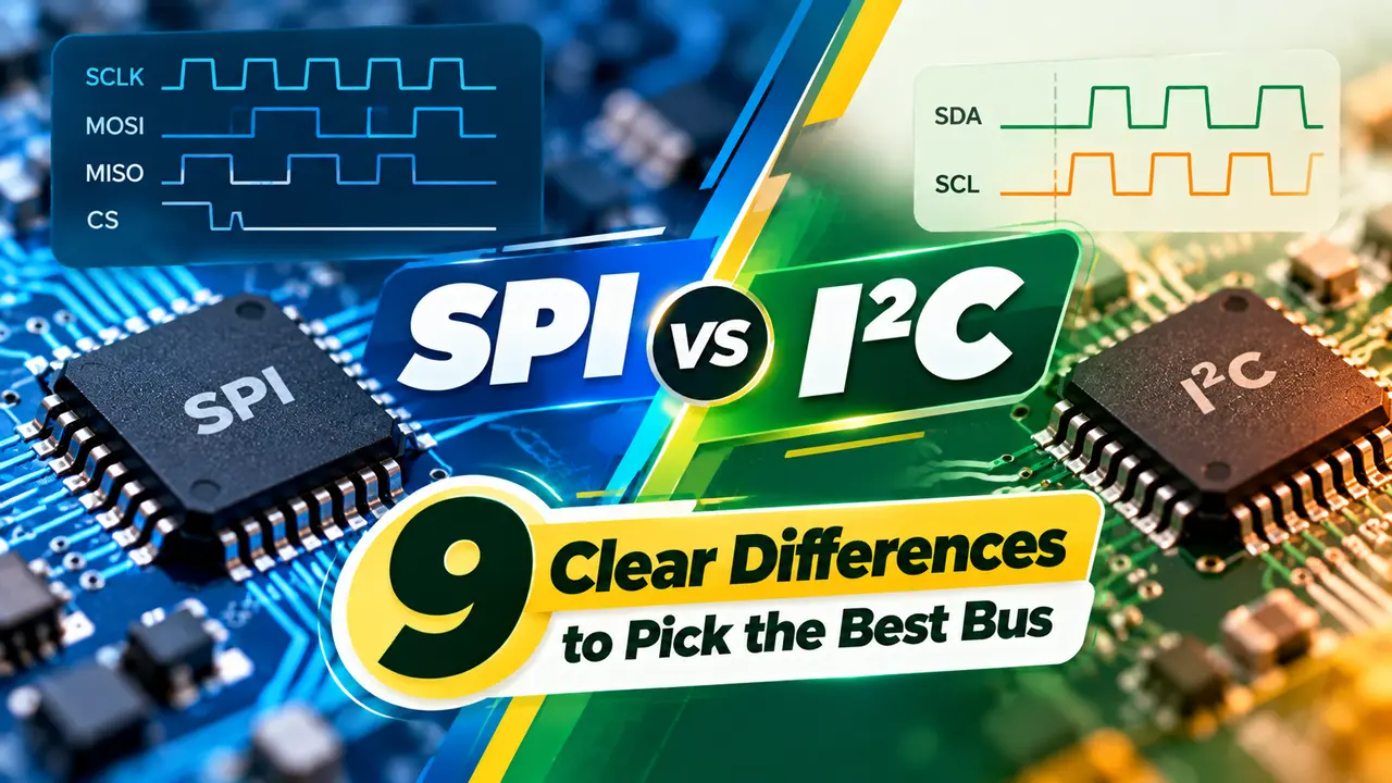
SPI vs I2C at a Glance
The SPI vs I2C question comes up in almost every microcontroller project. SPI, the Serial Peripheral Interface, uses separate data lines for each direction plus a chip select per device, while I2C, the Inter Integrated Circuit bus, shares two open drain lines between all devices and selects them by address, both being forms of serial communication.
Total Phase summarises the core split: I2C needs two wires and SPI needs four. SPI is full duplex, while I2C is half duplex.

Both are controlled by a microcontroller peripheral, so firmware rarely needs to bit bang the signals. Both are meant for short distances on one board or between nearby boards.
For longer cables between cabinets, industrial buses such as those in RS232 vs RS485 are more suitable.
9 Clear Differences
| Feature | SPI | I2C |
|---|---|---|
| 1. Wires | SCLK, MOSI, MISO, CS | SDA, SCL |
| 2. Device select | One chip select per device | 7 or 10 bit address |
| 3. Duplex | Full duplex | Half duplex |
| 4. Speed | Tens of MHz, above 100 MHz possible | 100 kHz, 400 kHz, 1 MHz, 3.4 MHz |
| 5. Acknowledge | None | ACK or NACK every byte |
| 6. Output type | Push pull | Open drain with pull ups |
| 7. Multi controller | Difficult | Supported |
| 8. Pin count growth | One CS pin per device | No extra pins |
| 9. Overhead | Very low | Address and ACK bits |
Total Phase notes that SPI has no defined maximum speed and has run above 100 MHz. Standard mode I2C runs at 100 kHz, with faster modes defined up to 3.4 MHz.
The TI SPI guide also highlights that SPI selects devices with chip select lines, while I2C selects them by address. That one difference drives most of the other tradeoffs.
How SPI Moves Data
SPI has four modes set by clock polarity CPOL and clock phase CPHA. Controller and peripheral must use the same mode, or data will be shifted on the wrong edge.
Because there is no acknowledge, the controller cannot tell if a device is missing. Firmware often reads an ID register at start up to check.
How I2C Moves Data
Every device only pulls lines low, and pull up resistors bring them high. This lets many devices share the bus safely and allows clock stretching by slow peripherals.
The wired AND behaviour comes from open drain outputs, a concept linked to digital logic gates. Address clashes are the most common I2C problem when adding identical sensors.
I2C Pull Up Resistor Formula
Rp max = tr ÷ (0.8473 × Cb)
tr = maximum rise time, 1000 ns standard mode, 300 ns fast mode, Cb = bus capacitance
Worked example, 3.3 V, fast mode, Cb = 200 pF:
Rp min = 2.9 ÷ 0.003 = 967 Ω
Rp max = 300 ns ÷ (0.8473 × 200 pF) = 1770 Ω
Choose 1.5 kΩ
Too small a resistor exceeds the 3 mA sink limit, and too large a resistor gives slow edges. Long traces add capacitance, which is why I2C struggles beyond a metre or so.
For fast SPI clocks, keep traces short and matched, following high speed signal integrity practice.
Which Bus to Choose
Highest speed and simple timing.
Fewest pins and many devices.
Most controllers support both at once.
UART, CAN or RS485 for cables.
High speed data converters usually prefer SPI, as seen in ADC designs. Slow sensors that report every second fit I2C nicely.
In the SPI vs I2C choice, pin count often decides. A controller with few free pins can still host a dozen I2C sensors.
Pull Up Resistor Calculator
If no valid value exists, shorten the bus, reduce device count or use a buffer IC. Active pull up devices also help on long buses.
- Very high speed.
- Full duplex transfers.
- Simple hardware.
- No address conflicts.
- Only two wires.
- Many devices share one bus.
- Acknowledge on every byte.
- Multi controller support.
TI Understanding the SPI Bus PDF
I2C and SPI Compared Video
SPI vs I2C FAQ
Related Articles
- What Is Serial Communication
- Microcontroller Working Principle
- Types of Communication Protocols
- RS232 vs RS485
- ADC Working Principle
External References
- Understanding the SPI Bus, Texas Instruments
- Differences Between I2C and SPI, Total Phase
- I2C, Wikipedia
What We Learn Today
- SPI uses four wires and chip selects for high speed full duplex links.
- I2C uses two open drain wires, addresses and pull ups.
- Settle SPI vs I2C by speed, pin count and number of devices.