
When the AC supply fails, every relay, breaker coil and SCADA panel in a substation runs on the station battery. Correct sizing with the IEEE 485 duty cycle method makes sure that battery still trips the last breaker at the end of its life.
A substation battery must carry trip coils, relays and emergency lighting for hours with no charger support. Proper battery sizing with a duty cycle, correction factors and the right cell count keeps protection working when it matters most.

What Is Battery Sizing for a Substation?
Battery sizing is the calculation of the ampere hour capacity and the number of cells a stationary battery needs so it can supply every DC load in its duty cycle, down to a chosen end voltage, at the lowest expected temperature and at the end of its service life. In a substation this battery feeds protective relays, breaker trip and close coils, SCADA and emergency lights.
The battery floats in parallel with a charger and the load, so on a normal day it does almost nothing. Once the charger loses AC input, it alone must hold the DC bus inside the voltage window of every device.
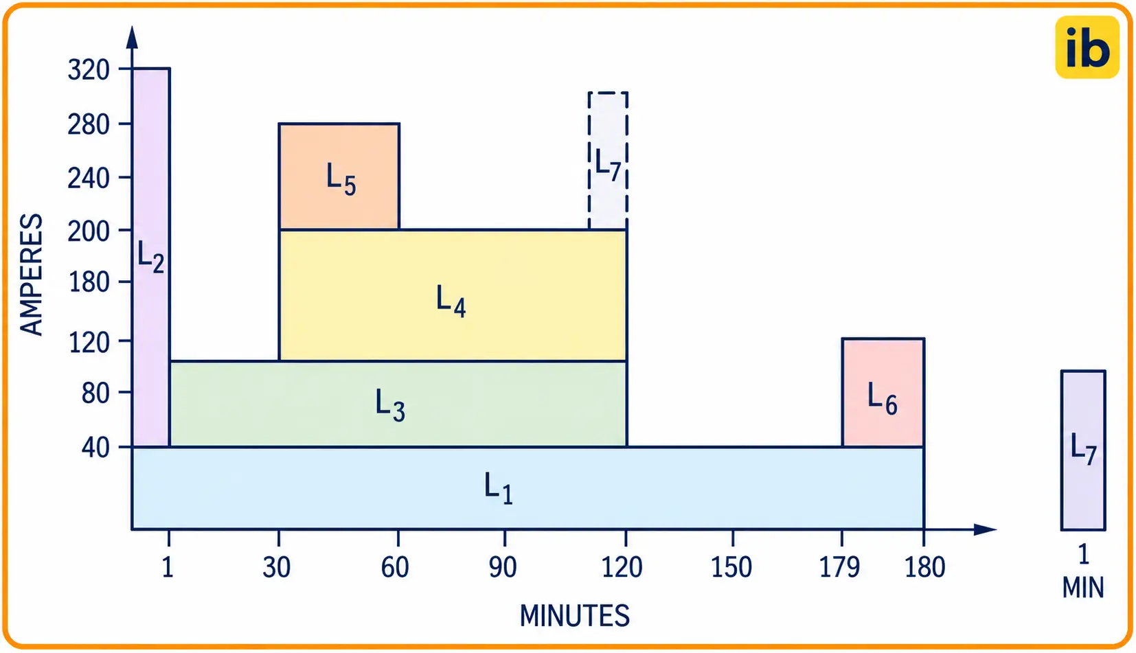
The figure above shows a typical duty cycle, the backbone of every IEEE 485 calculation. The same thinking applies to a UPS bank, but there the load is a constant power inverter, as covered in UPS capacity kVA calculation.
Standards Behind Substation Battery Sizing
IEEE Std 485 is the recommended practice for sizing lead acid batteries for stationary applications in full float operation. Nickel cadmium cells follow IEEE Std 1115, while IEEE 450 and IEEE 1188 cover maintenance and testing of vented and valve regulated lead acid batteries.
In India, utility specifications usually call for tubular positive plate cells to IS 1651 or VRLA cells, with 220 V or 110 V DC for protection and control and 48 V for communication equipment. The battery sizing method stays the same at any voltage.
Jim McDowall of Saft explains that the 1.25 aging factor exists because IEEE treats a lead acid battery as worn out at 80% of rated capacity. Since 80% × 125% = 100%, the bank still meets its duty on its last day.
Load Classes for Battery Sizing
Energised for the whole duty cycle, such as relays, indication lamps, SCADA RTUs and inverters for communication.
Run for part of the cycle, such as emergency lighting, fire pumps or motor operated isolators.
Last one minute or less, such as breaker trip coils, closing coils and motor inrush.
myElectrical notes that momentary loads are usually assumed to last a full minute in the calculation. Art Salander of C&D Technologies goes further and states that no event, for sizing purposes, is ever less than one minute when sizing lead acid cells.
A typical 220 kV substation duty cycle has a heavy first minute when several breakers trip together, a long continuous section, and a last minute when breakers close again after restoration. Trip coil currents come from breaker data, as in ACB, VCB and SF6 circuit breakers.
Collect real trip and close coil currents from breaker nameplates instead of guessing. Add every breaker that a busbar or breaker failure scheme can trip at the same time.
7 Proven Steps of Battery Sizing With IEEE 485
These seven steps turn a list of currents into a real cell size. Battery sizing is iterative, because the cell type chosen in the last step may have slightly different Kt values from the ones you assumed first.
Cell Count and End Voltage per Cell
In battery sizing, the number of cells is limited by the highest voltage the loads can tolerate during boost or equalise charging. The end voltage per cell then follows from the lowest voltage the loads need while the battery discharges.
End voltage per cell = Minimum bus voltage ÷ Number of cells
Example, 110 V DC system:
Maximum allowed = 121 V, equalise = 2.25 V per cell
Cells = 121 ÷ 2.25 = 53.8, so use 53 cells
Minimum allowed = 93.5 V
End voltage = 93.5 ÷ 53 = 1.76 V per cell
Here the manufacturer table for 1.75 V per cell is used, which is slightly conservative. Remember to include cable voltage drop between the battery and the farthest panel, using the method in voltage drop calculation, because the relay sees the panel voltage, not the terminal voltage.
A lower end voltage lets each cell deliver more ampere hours, so the bank gets smaller. The price is a lower bus voltage, which some old electromechanical relays and trip coils may not accept.
Battery Sizing Formula and Correction Factors
IEEE 485 sizes each section of the duty cycle separately and keeps the largest result. For one constant load the section reduces to the load current multiplied by a capacity rating factor Kt for that duration and end voltage.
Required capacity = F max × Temperature factor × (1 + Design margin) × Aging factor
Kt = rated Ah ÷ current a cell can supply for time t to the end voltage
Example, single continuous load:
Load = 40 A for 8 hours, Kt = 8.5 from the cell table
F = 40 × 8.5 = 340 Ah
340 × 1.11 temperature factor = 377.4 Ah
377.4 × 1.10 design margin = 415.14 Ah
415.14 × 1.25 aging factor = 518.93 Ah
The temperature factor of 1.11 is an example value for a battery room near 16 °C, because capacity falls as the electrolyte cools. Always take the factor from IEEE 485 or the cell manufacturer for your lowest expected room temperature.
myElectrical states that a design margin of 10% to 15% is common, to cover future loads, less than perfect maintenance and a battery that is not fully recharged. The final 518.93 Ah would lead you to the next standard size, for example a 600 Ah cell.
Battery Sizing Calculator
Second Worked Example: Two Section Duty Cycle
For this battery sizing example, take 100 A for the first minute while breakers trip, then 40 A until 120 minutes. Assume a cell table gives Kt of 0.625 for 1 minute, 2.70 for 120 minutes and 2.69 for 119 minutes, all to 1.75 V per cell.
| Section | Calculation | Result |
|---|---|---|
| Section 1, first minute | 100 × 0.625 | 62.5 Ah |
| Section 2, period 1 | 100 × 2.70 | 270.0 Ah |
| Section 2, period 2 | (40 minus 100) × 2.69 | minus 161.4 Ah |
| Section 2 total | 270.0 minus 161.4 | 108.6 Ah |
| Largest section | Section 2 | 108.6 Ah |
Section 2 governs at 108.6 Ah. Applying 1.11 for temperature, 1.10 for design margin and 1.25 for aging gives 108.6 × 1.11 × 1.10 × 1.25 = 165.75 Ah, so a 200 Ah cell is the practical choice.
The negative term simply removes the current that stops after the first minute. Salander places a random load, such as a fire pump, at the end of the worst section.
Keep the full battery sizing sheet with the Kt table version you used. During a future load addition, the same sheet shows quickly whether the existing bank still has margin.
Temperature, Aging and Margin in Battery Sizing
Lead acid capacity is rated at 25 °C, and a cold battery room in a hill station or a winter night in north India gives noticeably less ampere hours. Hot rooms do not justify a smaller bank, since heat shortens life.
The aging factor covers capacity loss through the years, and the C&D paper ties it to IEEE 450, where a battery is replaced once capacity falls to 80%. Common causes of early loss are discussed in causes of battery failure.
Lead Acid or NiCd for Substations
- Lower first cost per Ah.
- Familiar to most Indian utilities.
- Sized by IEEE 485 with the 1.25 aging factor.
- Easy to source as IS 1651 tubular cells.
- Higher first cost per Ah.
- Better at low temperatures and high rates.
- Sized by IEEE 1115 with its own factors.
- Longer life in harsh, hot or remote sites.
The battery does not work alone, because the charger must recharge it after an outage while still feeding the standing load. Charger output current and the inverter or UPS topology on the AC side are sized after the battery is fixed.
Installation and Commissioning Checks
- Battery room ventilated for hydrogen and kept near 25 °C.
- Cell count and connection polarity match the drawing.
- Intercell connectors torqued to the maker value.
- Float and boost voltages set per cell on the charger.
- Battery fuse or MCCB rated for the prospective fault current.
- DC earth fault monitoring tested on both poles.
- Initial discharge test recorded against the design sheet.
Size the main fuse and cables for the highest duty cycle current and check selectivity with downstream fuses, following the fuse selection guide and cable size for load current. A battery short circuit can deliver many kiloamperes, so the protective device must break that current safely.
For time based backup estimates on small systems, such as a panel UPS, the simpler rule in calculate battery backup time is fine. For protection DC in a substation, always use the full battery sizing method above.
Common Battery Sizing Mistakes
The last point matters in India, where many substations add bays years after commissioning. Whether the yard is GIS or AIS, list the future breakers in the load table, and remember that IEC 61850 substation automation adds network switches and IEDs that draw continuous DC.
IEEE 485 Practical Paper PDF
Substation Battery Sizing Video
Battery Sizing FAQ
It is the calculation of the ampere hour capacity and cell count that the station battery needs for its full duty cycle. The battery must reach the chosen end voltage only after supplying every load.
The method also allows for low temperature, future loads and capacity loss with age. IEEE 485 is the usual reference for lead acid cells.
Lead acid batteries are normally replaced when capacity falls to 80% of rating. Multiplying the required capacity by 1.25 means the bank still delivers 100% of the duty at that point.
Jim McDowall of Saft explains this logic in his Battcon paper on aging factors. It also raises cost and weight by roughly the same proportion.
Divide the minimum allowed DC bus voltage by the number of cells in the string. Values near 1.75 V per cell are common for lead acid substation batteries.
Check the lowest voltage that relays, trip coils and DC converters accept. A higher end voltage is safer for old devices but needs a bigger bank after battery sizing.
Divide the highest voltage the loads accept by the equalise voltage per cell. With 121 V and 2.25 V per cell, the result is 53 cells.
Utilities may choose a slightly different count to suit their charger float and boost settings. Always confirm the final count against both the maximum and minimum bus voltage of the system.
Several breakers can trip at once during a bus fault, and each trip coil draws a large current. A short high current needs much more capacity than its ampere hours suggest.
Many substation banks are therefore set by the first minute in battery sizing, not by the long continuous load. Salander treats every event as at least one minute long.
myElectrical reports that 10% to 15% is common in practice for station batteries. It covers future feeders, imperfect maintenance and a battery that is not fully charged after an outage.
Do not confuse it with the aging factor, which covers the gradual loss of capacity with age. Both are applied together, one after the other, in good battery sizing.
Nickel cadmium cells are sized with IEEE 1115 rather than IEEE 485 used for lead acid. The duty cycle idea is similar, but correction factors and aging behaviour differ noticeably.
McDowall notes that NiCd has no definite end of life point like lead acid, though many users still apply 80%. Follow the manufacturer data and the NiCd standard for those factors.
Related Articles
- Calculate Battery Backup Time
- Causes of Battery Failure
- UPS Capacity kVA Calculation
- Voltage Drop Calculation
- Fuse Selection Guide
External References
- Practical Applications of IEEE Std 485, Battcon
- Battery Sizing Notes, myElectrical Engineering
- Lead Acid Battery, Wikipedia
What We Learn Today
- Battery sizing with IEEE 485 splits the load profile into sections, multiplies currents by Kt factors and keeps the largest section result.
- Correction factors for temperature, a design margin of 10% to 15% and the 1.25 aging factor make sure capacity lasts the full battery life.
- Cell count comes from the highest allowed bus voltage, and the end voltage per cell comes from the lowest voltage the loads accept.