
Heavy loads like crushers, ball mills and cranes need huge torque from standstill without pulling a damaging current from the grid. The wound rotor motor solves this by letting you add resistance to the rotor circuit and remove it step by step as the machine speeds up.
A wound rotor motor brings its rotor winding out through slip rings so external resistance can shape its torque and current. This guide covers construction, working, starting, speed control and maintenance with a torque calculator.
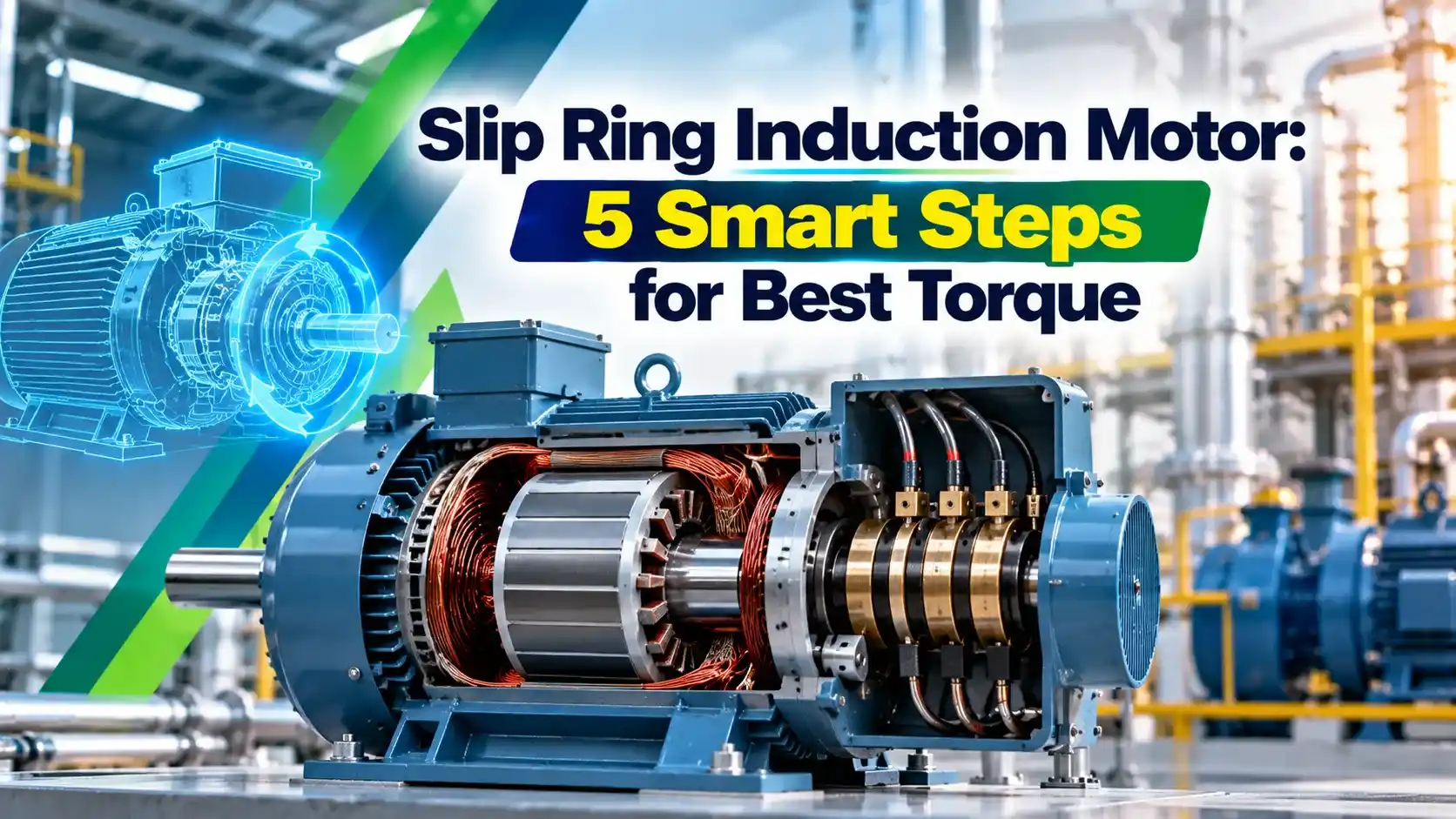
What Is a Slip Ring Induction Motor?
A slip ring induction motor is a 3 phase induction motor whose rotor carries a 3 phase insulated winding, brought out through three slip rings and carbon brushes to an external resistance bank. It works on the same rotating field principle described in how an AC induction motor works, but the rotor circuit can be changed from outside.
Because of this winding, the slip ring induction motor is also called a wound rotor motor. Electrical4u describes it as a special 3 phase induction motor designed to provide high starting torque by connecting an external resistance to the rotor circuit.

The curves above show the key idea. As rotor resistance increases, the peak torque stays the same but moves towards standstill, so the motor can deliver its maximum torque right at starting.
Construction of a Wound Rotor Motor
Laminated core with a 3 phase distributed winding, identical to a squirrel cage machine.
Laminated rotor with a 3 phase star connected insulated winding, wound for the same pole count.
Three copper or bronze rings on the shaft, insulated from it and from each other.
Carbon or metal graphite brushes, often with a short circuiting and brush lifting gear.
The stator is the same as in any cage motor, and the rotor winding is normally star connected with its three ends taken to the rings. The rotor insulation must withstand the open circuit rotor voltage, which can reach several hundred volts on large machines, so its class is chosen as carefully as described in motor insulation classes.
Electrical4u notes that wound rotor machines make up roughly 5 to 10 percent of industrial motors, while squirrel cage motors account for about 90 percent. Their share is small but they dominate heavy duty drives in cement, mining and steel plants.
Many large wound rotor motors have a brush lifting device that shorts the slip rings and lifts the brushes once full speed is reached. This removes brush friction and wear during normal running.
How a Slip Ring Induction Motor Works
The induced rotor voltage follows Faraday law of electromagnetic induction. At standstill the slip is 1, so rotor voltage and frequency are at their highest, and they fall in proportion to slip as the rotor speeds up, as explained in induction motor slip.
Adding external resistance has two effects at start. It limits rotor current, and therefore stator current, and it improves the rotor power factor so the current that does flow produces more useful torque.
Torque Equation of a Slip Ring Induction Motor
For an induction motor, maximum torque occurs at the slip where rotor resistance equals rotor reactance at standstill. The value of maximum torque itself does not depend on rotor resistance, which is why the whole curve can be shifted.
Starting torque ratio: Tst ÷ Tmax = 2 × sm ÷ (1 + sm²)
R2 = total rotor resistance per phase, internal plus external
X2 = rotor reactance per phase at standstill
Example: internal R2 = 0.2 Ω, external = 0.3 Ω, X2 = 1.0 Ω
sm = (0.2 + 0.3) ÷ 1.0 = 0.50
Tst ÷ Tmax = 2 × 0.5 ÷ (1 + 0.25) = 0.80
Starting torque = 80 percent of maximum torque
External resistance for full torque at start = 1.0 minus 0.2 = 0.8 Ω
With no external resistance the same rotor gives sm = 0.2 and a starting torque of only about 38 percent of maximum. The external resistance therefore more than doubles the starting torque while also reducing the starting current.
Rotor Resistance and Starting Torque Calculator
5 Steps to Start a Wound Rotor Motor
An interlock prevents the stator from closing unless the rotor resistance is fully in circuit. Without it, a slip ring induction motor started with shorted rings draws a direct on line current, defeating the purpose described in motor starting methods compared.
Sizing the resistor steps is a balance between smooth acceleration and resistor heating. Each step is usually set so the current peaks near 1.5 to 2 times full load current, which keeps the voltage dip within limits found in a motor starting voltage dip calculation.
Check the step timers against the actual load. A timer that cuts resistance before the motor has gained speed causes a current surge and a torque jerk on couplings and gearboxes.
Types of Rotor Starters and Controllers
| Starter Type | How It Works | Typical Use |
|---|---|---|
| Metal grid resistor | Steel or cast iron grids shorted by contactors in steps | Cranes, hoists, small mills |
| Liquid rheostat | Electrodes move in soda solution for stepless resistance | Large mills and crushers |
| Rotor thyristor control | Electronic switching varies effective rotor resistance | Retrofits, soft acceleration |
| Stator VFD | Variable frequency drive with rings permanently shorted | Modern speed control upgrades |
Liquid resistance starters give a smooth, stepless start and are common for high power mill drives in India. Smaller cranes still use drum controllers and grid resistors, while many plants now short the rings and add a VFD for speed control.
A soft starter on a wound rotor machine with shorted rings reduces current by lowering stator voltage, but it also cuts torque by the square of voltage. For high inertia loads this may leave too little torque, so the rotor resistance method is often kept.
Slip Ring vs Squirrel Cage Induction Motor
| Feature | Slip Ring Motor | Squirrel Cage Motor |
|---|---|---|
| Rotor | 3 phase insulated winding | Bars shorted by end rings |
| Starting torque | High, adjustable | Fixed, moderate |
| Starting current | Low, controlled | 5 to 8 times full load with DOL |
| Speed control | Rotor resistance or slip recovery | Needs VFD |
| Maintenance | Brushes and rings need care | Very low |
| Cost | Higher | Lower |
For most pumps and fans, a cage motor with a DOL or star delta starter is cheaper and simpler. The slip ring induction motor earns its place when the load needs high torque at standstill on a weak supply.
Speed Control and Slip Power Recovery
Keeping some resistance in the rotor during running lowers the speed, because more slip is needed to produce the same torque. The price is efficiency, since rotor copper loss equals slip times air gap power.
Second worked example: a 100 kW air gap power at 30 percent slip means 0.3 × 100 = 30 kW becomes heat in the rotor resistors. Only 70 kW reaches the shaft, which is why resistance speed control suits only short duty such as crane hoisting.
Slip power recovery schemes avoid this waste. The Kramer drive rectifies rotor power and returns it through a motor or inverter, while the static Scherbius drive feeds it back to the supply.
Doubly fed machines use the same wound rotor idea in wind turbines, where the rotor converter controls both motor and generator action described in AC motors and generators. A modern wound rotor drive can therefore save energy instead of burning it.
Most modern wind turbines in the 1.5 to 3 MW range use doubly fed wound rotor generators. A converter rated near 30 percent of turbine power controls the rotor, which keeps the cost of power electronics low.
Applications of the Slip Ring Induction Motor
ABB, in its slip ring motors brochure, lists outputs up to 10000 kW at 2.3 to 13.8 kV for heavy load inertia drives such as mills, cement, mining and water pumping stations. It highlights high starting torque and low starting current as the reason these motors suit weak networks.
Slip Ring Induction Motor Maintenance and Troubleshooting
- Measure brush length and replace before the wear mark.
- Check brush spring pressure and free movement in holders.
- Inspect slip rings for grooves, ovality and black film.
- Clean carbon dust from the ring enclosure and insulation.
- Test rotor and stator insulation resistance.
- Verify resistor bank connections and contactor tips.
- Confirm the short circuit and brush lift gear operates fully.
Sparking at the rings usually means worn brushes, wrong grade, low spring pressure or a rough ring surface. Measure rotor winding insulation with an insulation resistance tester, remembering that the rotor test voltage is based on the open circuit rotor voltage on the nameplate.
If the motor runs slow and hot, check whether one rotor phase is open or the rings are not fully shorted. Protection relays of the type described in motor protection relay types detect the resulting unbalance and overload.
Never let the rotor circuit stay open while the stator is energised, because the open rotor voltage can be dangerous at the rings. Lock out both the stator supply and the rotor starter before touching the brush gear.
- High starting torque, up to maximum torque at standstill.
- Low starting current that protects weak networks.
- Smooth, controlled acceleration of high inertia loads.
- Speed control and slip power recovery are possible.
- Brushes and slip rings need regular maintenance.
- Higher cost and larger size than cage motors.
- Resistance speed control wastes energy.
- Brush sparking limits use in hazardous areas.
ABB Slip Ring Motors Brochure
Wound Rotor Motor in Industry Video
Slip Ring Induction Motor FAQ
It is a 3 phase induction motor whose rotor has a 3 phase insulated winding connected to three slip rings. Brushes on the rings let external resistance be added to the rotor circuit.
This resistance raises starting torque and lowers starting current. Once the motor reaches speed, the rings are shorted and it runs like a cage machine.
The slip at maximum torque equals rotor resistance divided by rotor reactance at standstill. Adding resistance therefore shifts the point of maximum torque towards zero speed.
It also improves the rotor power factor at start, so more of the current produces useful torque. When total resistance equals reactance, the motor gives its maximum torque right at standstill.
No, the value of maximum torque stays the same whatever the rotor resistance is. Only the slip at which that maximum occurs changes with the resistance.
This is why a family of torque speed curves for a wound rotor motor all reach the same peak height. The peaks simply move left or right along the speed axis as resistance changes.
They drive cranes, hoists, crushers, ball mills, cement kilns, long conveyors and large compressors. These loads need very high torque from rest or a carefully controlled start.
They also suit sites with weak supplies where a direct on line start would cause a deep voltage dip. Doubly fed wind generators use the same rotor design on a much larger scale.
Brushes wear and must be measured and replaced before they reach the wear limit mark. Slip rings need regular inspection for grooves, ovality, sparking marks and uneven film.
Carbon dust must be cleaned regularly to avoid tracking across the insulation. The resistor bank, starter contactors and short circuit gear also need periodic checks and tightening.
Speed can be reduced by leaving resistance in the rotor, which increases slip for the same load torque. The extra slip power is wasted as heat in the resistor bank.
Slip power recovery drives such as Kramer and static Scherbius return that power instead of wasting it. Today many plants short the rings and add a variable frequency drive on the stator.
A soft starter lowers the stator voltage, and motor torque falls with the square of that voltage. For light loads this can work well with the rings permanently shorted.
For crushers and mills the reduced torque may be too low to break away the stuck load. The rotor resistance method usually remains the better and safer choice for such drives.
Related Articles
- How an AC Induction Motor Works
- Induction Motor Slip Explained
- Motor Starting Methods Compared
- Soft Starter Working Principle
- Motor Protection Relay Types
External References
What We Learn Today
- A slip ring induction motor has a 3 phase wound rotor brought out through slip rings, so external resistance can be added to shape torque and current.
- Slip at maximum torque equals R2 divided by X2, so raising rotor resistance moves peak torque towards standstill without changing its value at all.
- Resistance is cut out in steps during starting, then rings are shorted, while slip power recovery drives avoid wasting rotor power as heat.