
These three circuit families all switch between output states using the same basic timer building block, but each one holds those states for a completely different reason.
An Astable vs Monostable vs Bistable Multivibrator comparison comes down to stability, how long each circuit stays in a given output state before switching on its own or waiting for a trigger.
All three configurations are commonly built around a 555 timer IC, and understanding digital logic gates helps explain how the internal flip flop inside that chip actually latches each state.

Astable vs Monostable vs Bistable Multivibrator: The Core Idea
An astable circuit has no stable state at all, continuously switching back and forth between high and low output on its own, which makes it the basis of most square wave oscillators.
A monostable circuit has exactly one stable state, sitting quietly until an external trigger arrives, then producing a single output pulse of a fixed duration before returning to rest.
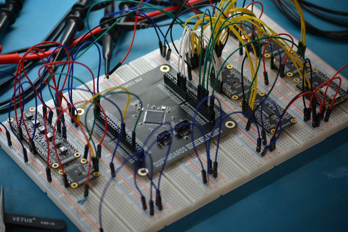
A bistable circuit has two stable states and needs a separate trigger to move between each one, holding whichever state it is in indefinitely until that next trigger arrives.
4 Steps to Identify Which Circuit You Have
Key Characteristics at a Glance
Free running oscillator, continuously toggling output with no external trigger needed.
Produces one fixed length pulse each time an external trigger is applied.
Holds one of two output states until a separate trigger flips it to the other.
Output Waveform Comparison
Astable Frequency Formula
Example:
R1 = 1 kilohm, R2 = 10 kilohm, C = 1 microfarad
Frequency = 1.44 divided by (21000 times 0.000001)
Frequency = 1.44 divided by 0.021 = 68.6 Hz
The same 555 timer IC that builds an astable oscillator can also drive a MOSFET switching stage, letting a simple timing circuit control much larger loads.
Where Each Circuit Is Used
Common Mistakes in Multivibrator Design
Confusing which resistor sets the charge time and which sets the discharge time is a frequent error in astable 555 circuits, leading to a duty cycle far from what was intended.
For monostable designs, forgetting that the trigger pulse itself must be shorter than the output pulse duration causes retriggering and an output that never actually returns to rest.
In bistable circuits built from discrete transistors rather than an IC, skipping proper base resistor sizing, much like sizing decisions covered in diode types selection, can leave the circuit stuck between states instead of switching cleanly.
Noise on the trigger input is another shared risk across all three circuit types, since a false trigger edge can start an unwanted pulse or flip a latch at the wrong moment.
Component tolerance is worth checking too. Standard resistors and capacitors carry a five or ten percent tolerance, so a calculated frequency or pulse width can drift noticeably from the design target once real parts are installed.
Supply voltage variation affects timing accuracy as well. Most 555 timer designs stay reasonably stable across a wide supply range, but precision applications benefit from a regulated supply, comparing linear vs switching voltage regulators, rather than a battery that sags under load.
Layout also plays a role that is easy to overlook. Long timing capacitor leads pick up stray capacitance from nearby traces, which can shift the effective RC time constant enough to matter in a tightly specified design.
Astable Frequency Calculator
Reference Document
Watch: 555 Timer in All Three Modes
Frequently Asked Questions
Related Articles
- Digital Logic Gates Explained
- MOSFET Working Principle
- Linear vs Switching Voltage Regulators
- What Is a Zener Diode?
- Diode Types Explained
External References
What We Learn Today
- Astable, monostable, and bistable circuits differ mainly in how many stable output states they have.
- The same 555 timer IC can be wired to build any of the three, just by changing a few components.
- Choosing the right type depends on whether the application needs a clock, a delay, or a memory latch.