
A digital input that is left unconnected picks up noise and reads random highs and lows, which makes buttons, sensors and buses behave strangely. One correctly chosen resistor gives that pin a defined default state and keeps your logic calm and predictable.
Every button, open drain output and I2C bus depends on a resistor that quietly holds the line at a known level. Choosing that value well is a simple balance between speed, power and noise immunity.

What Is a Pull Up Resistor?
A pull up resistor is a resistor connected between a signal line and the positive supply, so that the line sits at a logic high whenever nothing else is driving it. It is one of the most common parts on any microcontroller board, yet many beginners only notice it when an input starts misbehaving.
The reason is simple: a CMOS input has a very high impedance and draws almost no current. As explained in TTL vs CMOS logic families, such an input left open behaves like a tiny antenna and can settle anywhere between 0 and Vcc.
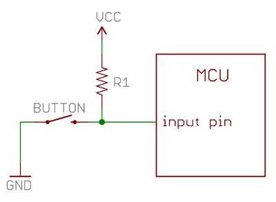
In the schematic, the resistor holds the pin high while the button is open. When the button is pressed, the pin connects directly to ground and reads low, while the resistor limits the current that flows from Vcc to ground.
SparkFun notes that microcontroller input pins typically present an impedance of about 100 kΩ to 1 MΩ. That is why even a fairly large resistor can hold such a pin firmly at a defined level.
Why Floating Inputs Cause Trouble
A floating input has no defined voltage, so nearby wiring, mains hum or a finger near the board can push it across the switching threshold. The result is random toggling, false interrupts and extra current, because a CMOS gate drawing a mid level voltage turns on both of its output transistors partly, which is also discussed in noise reduction techniques for digital ICs.
Pull Up vs Pull Down Resistor
A pull down resistor does the opposite job: it connects the line to ground, so the default state is low and a switch to Vcc makes it high. Both use the same value logic, and the choice depends on which default state is safe for your circuit.
- Default state is logic high.
- Button or open drain output pulls the line low.
- Natural choice for I2C, reset pins and open collector outputs.
- Matches active low signals common in digital ICs.
- Default state is logic low.
- Button or sensor drives the line high.
- Useful where an output must stay off at power up.
- Common on MOSFET gates and enable pins.
Active low pins such as nRESET or chip select almost always want a pull up resistor. For a MOSFET gate driven from a microcontroller, a pull down is preferred so the transistor stays off while the controller boots.
Decide the safe state first, then choose pull up or pull down. Ask what the output should do if the controller is in reset, unprogrammed or has a broken wire, and let that answer decide.
How the Pull Up Resistor Value Works
The resistor and the input impedance of the pin form a simple divider, as described in voltage divider rule. If the resistor is too large compared with the input impedance or leakage current, the pin voltage drops toward the undefined region.
SparkFun suggests keeping the pull up resistor at about one tenth of the input impedance, and recommends values from 10 kΩ to 100 kΩ for most switch inputs. When the button closes, the current is simply Vcc divided by R from Ohm’s law, so 5 V across 5 kΩ gives 1 mA.
A small pull up resistor gives faster edges and better noise immunity, but wastes current whenever the line is low. A large one saves power on battery devices, but makes the line slow and easier to disturb.
6 Simple Rules for Choosing Values
Rule two needs real numbers from the datasheet. If a pin leaks 1 µA and you use 100 kΩ, the drop is only 0.1 V, but a 1 MΩ resistor would drop 1 V and eat your margin, as the Schmitt trigger hysteresis article explains for threshold bands.
Rule four matters because every line has capacitance from pins, traces and cables. The rising edge follows the RC curve covered in RC and RL time constant, so 10 kΩ with 100 pF gives a time constant of 1 µs.
| Application | Typical Value | Reason |
|---|---|---|
| Push button on MCU pin | 10 kΩ to 47 kΩ | Low current, slow signal |
| Reset pin of MCU | 10 kΩ | Firm default, datasheet advice |
| I2C at 100 kHz | 4.7 kΩ to 10 kΩ | Meets 1000 ns rise time |
| I2C at 400 kHz | 1.5 kΩ to 2.2 kΩ | Meets 300 ns rise time |
| Open collector sensor to PLC | 1 kΩ to 4.7 kΩ | Noisy plant wiring, long cables |
| Battery powered switch | 100 kΩ to 470 kΩ | Minimum standby drain |
I2C Pull Up Resistor Formula
I2C lines are open drain, so devices can only pull them low and a pull up resistor must raise them high again. The bus is described in SPI vs I2C protocol comparison, and its speed limit comes from how fast that resistor can charge the bus capacitance.
Texas Instruments application note SLVA689 gives two limits. The minimum value keeps the sink current within what the weakest device can handle, and the maximum value meets the rise time from 30 percent to 70 percent of Vcc, which takes 0.8473 times RC.
Rp max = tr ÷ (0.8473 × Cb)
Standard mode: tr = 1000 ns, VOL = 0.4 V, IOL = 3 mA
Example: Vcc = 3.3 V, Cb = 200 pF
Rp min = (3.3 minus 0.4) ÷ 3 mA = 0.97 kΩ
Rp max = 1000 ns ÷ (0.8473 × 200 pF) = 5.90 kΩ
Any value from 0.97 kΩ to 5.90 kΩ works, so 4.7 kΩ is a good choice
TI also notes that a smaller resistor gives higher speed while a larger one gives lower power, and the I2C standard caps bus capacitance at 400 pF. In practice, a 4.7 kΩ pull up resistor is the classic choice for short 100 kHz buses.
I2C Pull Up Range Calculator
Second worked example: a fast mode bus at 400 kHz has tr = 300 ns, and with 200 pF at 3.3 V the maximum becomes 300 ÷ (0.8473 × 200) = 1.77 kΩ. The minimum stays at 0.97 kΩ, so a 1.5 kΩ resistor fits and 4.7 kΩ would be far too slow.
Each I2C device module often carries its own 4.7 kΩ or 10 kΩ pull ups. Connect three such modules and the effective resistance falls to a third, which can push the bus below Rp min.
Internal Pull Ups in Microcontrollers
Most microcontrollers have built in weak pull ups that firmware can switch on, such as INPUT_PULLUP in Arduino code. On the ATmega328P the internal value is specified between 20 kΩ and 50 kΩ, which is fine for buttons on short wires.
Internal pull ups are weak and loosely specified, so they are poor for I2C at 400 kHz, long cables or noisy panels. Fit an external pull up resistor close to the receiving pin instead.
When a board works on the bench but fails in the panel, measure the line with an oscilloscope for slow edges or ringing. Swapping a weak internal pull up for an external 4.7 kΩ often fixes it at once.
Open Drain and Open Collector Outputs
An open drain output has only a transistor to ground, so it can sink current but cannot drive high by itself. This allows several devices to share one line in a wired AND fashion, and it lets a 3.3 V chip signal a 5 V input simply by tying the pull up to the higher rail, much like the ideas in digital logic gates.
In plants, NPN proximity switches with open collector outputs follow the same rule, as described in NPN and PNP proximity sensors. A PLC sourcing input card provides its own internal pull up, which links to the ideas in sinking and sourcing in PLC.
Only an N channel transistor to ground, line pulled high externally.
NPN transistor to ground, same principle as open drain.
Drives both high and low actively, no pull up needed.
Common Mistakes With Pull Ups
Another frequent error is tying a pull up resistor to 5 V on a pin that is only 3.3 V tolerant. Check absolute maximum ratings first, and see RS485 termination and biasing resistors for a similar biasing idea on differential buses.
Inspection and Troubleshooting Checklist
- Confirm every input has a defined default state.
- Measure idle voltage on each line with a multimeter.
- Check the low level stays below VIL with all loads connected.
- Scope rise time on I2C and compare with the standard limit.
- Count all pull ups in parallel on shared buses.
- Verify the pull up rail matches the input voltage rating.
- Look for slow edges or ringing on long cables.
For field inputs such as a limit switch on a long cable, a lower value like 2.2 kΩ to 4.7 kΩ gives a stiffer line that resists induced noise. Use a metal film part from the resistor color code guide range, and the power is rarely an issue, since 5 V across 2.2 kΩ dissipates only about 11 mW.
Where Pull Ups Are Used
TI I2C Pullup Resistor Calculation Note
Pull Up and Pull Down Video Lesson
Pull Up Resistor FAQ
It connects a signal line to the positive supply so the line reads high when nothing drives it. This removes the floating condition that makes digital inputs read random values.
When a switch or transistor pulls the line to ground, the resistor limits the current that flows. The pin then reads low cleanly until the switch opens again.
For general switch inputs, 10 kΩ is the usual starting point on 3.3 and 5 volt boards. SparkFun recommends a range of 10 to 100 kΩ for most microcontroller inputs.
Fast lines such as I2C need smaller values, often between 2.2 and 4.7 kΩ in practice. Battery devices may use 100 kΩ or more to save standby current.
Use a pull down when the safe default state of a line is low. MOSFET gates, motor enables and heater outputs usually need this so loads stay off during power up.
The value rules are the same as for a pull up on that line. Only the connection changes, going to ground instead of the supply rail.
Calculate a minimum from the supply, the low level voltage and the sink current of the weakest device. Then calculate a maximum from the rise time limit and the bus capacitance.
Texas Instruments gives Rp max as tr divided by 0.8473 times Cb. Any standard value between the two limits will work on that bus.
They work well for buttons and short wires on a single board. The ATmega328P internal value lies between 20 and 50 kΩ, which is quite weak for many jobs.
For I2C at 400 kHz, long cables or noisy industrial panels, add an external pull up resistor instead. Place it near the receiving device for the cleanest result.
Each breakout board often carries its own resistors, and they all appear in parallel on the bus. Three 4.7 kΩ pull ups together behave like about 1.6 kΩ in total.
That can exceed the 3 mA sink limit of weaker devices. Remove the extra resistors from the modules so that only one pair remains on the whole bus.
It draws current only while the line is held low, equal to the supply voltage divided by the resistance. At 5 volts, a 10 kΩ part draws only 0.5 mA in that state.
Lines that idle high waste almost nothing at all. For lines that stay low for long periods, pick a larger value or rethink the logic polarity.
Related Articles
- TTL vs CMOS Logic Families
- SPI vs I2C Protocol Comparison
- Schmitt Trigger Hysteresis
- NPN and PNP Proximity Sensors
- Voltage Divider Rule Explained
External References
- I2C Bus Pullup Resistor Calculation SLVA689, Texas Instruments
- Pull up Resistors Tutorial, SparkFun Electronics
- Pull up Resistor, Wikipedia
What We Learn Today
- A pull up resistor ties an idle line to the supply so a high impedance CMOS input never floats and reads random values.
- Choose the value as a balance: small resistors give fast edges and noise immunity, while large ones save power on battery devices.
- For I2C, Rp min equals (Vcc minus VOL) ÷ IOL and Rp max equals tr ÷ (0.8473 × Cb) from the TI method.