
Parts on a conveyor leave a sensor in the same order they arrived, so the controller must remember that order until each part reaches a reject gate or a label printer. A queue held in an array, filled and emptied by two instructions, does exactly that job.
A queue lets a controller remember data in the order it arrived and hand it back in the same order later. Learn how FFL, FFU, LFL and LFU work, how Siemens users build the same queue, and how to size it for a conveyor.
What Is a PLC FIFO?
A PLC FIFO is a first in, first out queue built from an array, where the oldest value loaded is always the first value unloaded. It lets a program remember a sequence of part numbers, recipe codes or reject flags until a later station needs them, much like the word level moves explained in PLC data move instructions.
The opposite structure is LIFO, last in, first out, where the newest value comes back first like a stack of plates. Both live inside ordinary arrays, so the element type follows the rules in PLC data types.
A FIFO differs from a bit shift register because it moves only when an event happens, not on every clock pulse or encoder count. If you already know shift register SHL and SHR logic, think of a FIFO as an asynchronous shift register that accepts whole words or structures.
How FFL and FFU Instructions Work
Rockwell Automation documents FFL, FIFO Load, with five operands: Source, the FIFO array, a CONTROL tag, Length and Position. On each false to true rung transition, FFL copies the Source value into the array element pointed to by the position and then increments that position.
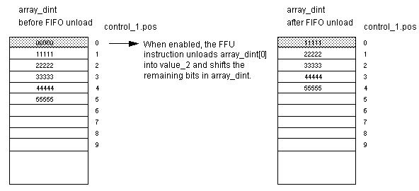
FFU, FIFO Unload, always takes the value at element zero, writes it to the Destination and shifts every remaining element down by one place. Rockwell states that it unloads one value each time it is enabled until the queue is empty, and it returns zero if nothing is left.
FFU: Dest = FIFO[0], shift all elements down, then .POS = .POS minus 1
Example, Length 4, loads 101, 102, 103:
Array = 101, 102, 103, 0 and .POS = 3
One FFU gives Dest = 101
Array = 102, 103, 0, 0 and .POS = 2
Because both instructions act on a rising edge, a part that stays in front of a sensor still loads only once. This is the same edge behaviour you meet with one shot ONS, OSR and OSF instructions, and it is essential for reliable PLC FIFO logic.
In Logix controllers the FIFO array can hold SINT, INT, DINT, REAL, STRING or a user defined structure. One FFL can therefore queue a complete part record with ID, weight and reject code in a single load.
The Control Word: EN, DN, EM, LEN and POS
Both instructions of a PLC FIFO pair must share one CONTROL tag, and Rockwell explicitly recommends using the same structure for FFL and FFU. Its members tell the program exactly what the queue is doing at every scan.
| Member | Type | Meaning in a PLC FIFO |
|---|---|---|
| .EN | BOOL | Load instruction is enabled by the rung |
| .EU | BOOL | Unload instruction is enabled by the rung |
| .DN | BOOL | Queue is full, .POS equals .LEN |
| .EM | BOOL | Queue is empty, .POS equals zero |
| .LEN | DINT | Maximum number of elements |
| .POS | DINT | Next load position, equal to items held |
Rockwell notes that the done bit inhibits further loads until the position falls below the length. A full PLC FIFO therefore silently ignores new data, which is why good programs alarm on .DN instead of just hoping it never happens.
On older SLC 500 and MicroLogix controllers, the same bits sit in an R6 control file, with EN at bit 15, EU at bit 14, DN at bit 13 and EM at bit 12. The addressing style is covered in PLC memory addressing.
Put an XIO of the .DN bit in front of FFL and an XIO of the .EM bit in front of FFU. You then get a clear alarm instead of lost or zero data when the queue overflows or runs dry.
LIFO With LFL and LFU
LFL loads data exactly like FFL, but LFU unloads the most recent value, taken from position minus one, and does not shift the array. LIFO suits stacking problems such as a pallet stacker or a magazine where the last plate placed is the first one removed.
- Conveyors and accumulation lanes keep arrival order.
- Print and label jobs must come out in sequence.
- Batch recipes are queued for a single reactor.
- Fault and downtime event logs keep history in order.
- Vertical stackers and magazines remove the top item first.
- Undo style operator actions return the last step.
- Tray buffers where only the top tray is reachable.
- Temporary storage of nested sequence states.
Building a PLC FIFO on Siemens S7 1200 and S7 1500
Siemens ladder has no direct FFL or FFU box, so engineers build the PLC FIFO from an array and a few lines of code, often in structured text or SCL. The S7 1200 and S7 1500 families handle this equally well.
The Siemens Library of General Functions offers the function block LGF_FIFO, which the library manual describes as storing incoming jobs and outputting the oldest job not yet processed. It is built as a ring buffer and uses the VARIANT data type, so one block can queue different data types.
Two indexes, head and tail, chase each other around a fixed array, so nothing physically moves.
Each unload copies element 1 onwards down by one, exactly like FFU.
Ready made LGF_FIFO with mode, status and generic data.
A shift array FIFO copies every remaining element on each unload, so a queue of 500 records does 499 copies per unload. A ring buffer only changes one index, which is why large queues in Siemens projects usually use it.
6 Practical Steps to Build a PLC FIFO
Step three deserves care because a chattering photo eye loads phantom parts. Choose a suitable sensor from types of photoelectric sensors and set the input filter so one part gives exactly one edge.
Conveyor Part Tracking With a PLC FIFO
Picture a bottle line where a vision camera at station one grades each bottle and a reject pusher sits six metres downstream. The camera result is loaded into the PLC FIFO as each bottle passes, and a second photo eye at the pusher triggers the unload.
The order holds because bottles cannot overtake each other on a single lane conveyor. If parts can be removed by hand or fall off, the PLC FIFO goes out of step, so many plants add a second check such as encoder based position from a high speed counter or a barcode reread.
Show the PLC FIFO .POS value on the HMI next to a count of parts physically on the belt. When the two numbers differ, operators see the tracking error at once instead of discovering it at the reject gate.
PLC FIFO Queue Sizing Calculator
The PLC FIFO must hold every part that can be between the load point and the unload point at the same time. With the shortest possible spacing between parts, that number is the distance divided by the minimum pitch, plus a safety margin for accumulation.
Recommended LEN = ceiling(N × (1 + Margin ÷ 100))
Travel time = Distance ÷ Belt speed
Example:
Distance 6 m, belt 0.5 m/s, minimum pitch 0.6 m, margin 25 %
N = 6 ÷ 0.6 = 10 parts
LEN = ceiling(10 × 1.25) = ceiling(12.5) = 13
Travel time = 6 ÷ 0.5 = 12.0 s
Second Worked Example: Accumulation Lane
A case conveyor is 18 m long between a labeller and a palletiser, and cases can accumulate nose to tail at a minimum pitch of 0.45 m when the palletiser stops. N is 18 ÷ 0.45 = 40 cases, and a 25 percent margin gives a length of 50.
With a belt speed of 0.6 m/s the normal travel time is 30 s, but accumulation can stretch it to minutes. That is why the PLC FIFO must never depend on a timer, unlike the fixed delay logic in timer instructions TON, TOF and RTO.
Common PLC FIFO Mistakes and Fixes
Writing outside the array is a third mistake, usually after someone changes .LEN online without enlarging the array. A Logix controller then raises a major fault, explained in PLC fault handling and recovery.
PLC FIFO Commissioning Checklist
- Array size is at least equal to the control .LEN value.
- FFL and FFU reference the same CONTROL tag.
- Entry and exit sensors give one clean edge per part.
- DN and EM conditions are interlocked and alarmed.
- Queue count is shown on the HMI with a reset button.
- Behaviour after power loss and line purge is defined.
- Test with parts removed by hand to confirm recovery.
Where a PLC FIFO Is Used in Industry
Logix Instruction Reference Manual
FIFO Load and Unload Video Example
PLC FIFO FAQ
It is a first in, first out queue held in an array, where the oldest stored value is always returned first. Controllers use it to remember part data until a later station needs it.
Rockwell controllers provide FFL to load and FFU to unload the queue. Siemens users build the same queue with a ring buffer or the LGF_FIFO library block.
EN shows that the load rung is enabled, while EU shows the same for the unload rung. DN turns on when the position equals the length, meaning the queue is full.
EM turns on when the position is zero and nothing is left to unload. Good programs block loads on DN, block unloads on EM and alarm both states.
A LIFO returns the newest value first, like taking the top plate from a stack. LFU reads the last loaded position and does not shift the array at all.
A FIFO returns the oldest value and shifts the remaining data down one place. Choose LIFO for stackers and magazines, and FIFO for conveyors and job queues.
Yes, Logix arrays can be built from a user defined structure holding part ID, weight and a reject code. A single load then stores the whole record in one step.
Keep the structure small because a shift style unload copies every element each time. Large records in a long PLC FIFO increase scan time noticeably.
They use an array with head and tail indexes, usually written in SCL as a ring buffer. Each write and read moves only an index, so execution time stays constant.
The Library of General Functions also offers LGF_FIFO with a VARIANT interface. It saves development time and has already been tested by Siemens across many different projects.
Divide the distance between the load and unload points by the smallest possible spacing between parts. Then add a margin of about 25 percent for accumulation and surges.
For 6 m and a minimum pitch of 0.6 m, ten parts can be in transit. A length of 13 elements then gives comfortable headroom for normal production.
The usual causes are a missed or doubled sensor edge, or a part removed by hand. Each event shifts every later record by one position in the queue.
Use clean one shot triggers, compare queue count with the parts on the belt and provide a reset. An encoder or barcode recheck catches errors before the reject gate acts.
Related Articles
- PLC Shift Register SHL and SHR
- PLC Bit Shift and Rotate Instructions
- PLC Data Move Instructions
- PLC One Shot ONS, OSR and OSF
- PLC Structured Text Programming
External References
- Logix 5000 Controllers General Instructions Reference Manual, Rockwell Automation
- FIFO Load (FFL) Instruction, Rockwell Automation
- FIFO in Computing and Electronics, Wikipedia
What We Learn Today
- A PLC FIFO is an array based queue where FFL loads at the position pointer and FFU always unloads element zero, so the oldest record leaves first.
- The shared CONTROL tag holds LEN and POS plus the EN, DN and EM bits, which tell you whether the queue is enabled, full or empty.
- Siemens has no FFL box, so engineers use an SCL ring buffer or LGF_FIFO, and queue length comes from distance divided by minimum part pitch.