
Every breaker trip coil, protection relay and emergency light in a substation depends on a DC supply that must never fail. The charger keeps that battery ready, so choosing the right modes, voltages and current rating is a job worth doing carefully.
Substations and process plants rely on a battery bank and charger to supply protection and control power around the clock. This guide explains float and boost charging, charger types and how to size the output current.

What Is an Industrial Battery Charger?
An industrial battery charger is a controlled rectifier that converts the AC auxiliary supply into regulated DC, feeds the continuous DC load of a substation or plant, and keeps a stationary battery fully charged. If the AC supply fails, the battery takes over instantly with no break, which is why the system works like a DC version of a UPS.
Typical DC loads are breaker trip and close coils, protective relays, annunciators, SCADA RTUs, DC emergency lighting and DC motors for spring charging. These loads must work during the very fault that may have caused the AC supply to fail.
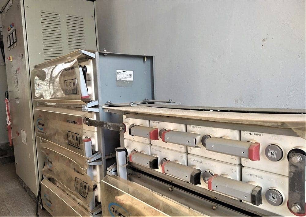
Every battery charger is matched to a DC system voltage. Common values in India are 24 V and 48 V for telecom and SCADA, and 110 V or 220 V for substation protection and control. Power stations often use 220 V with large flooded lead acid batteries, while 66 kV and 33 kV substations mostly use 110 V.
Inside a Substation DC System
The battery charger sits between the AC auxiliary board and the DC distribution board, with the battery connected across its output. Under normal conditions the charger supplies all load current plus a small float current into the battery, so the battery stays full without discharging.
Electrical Engineering Portal notes that lead acid batteries hold more than 90 percent of the industrial market, with VRLA cells expected to last 10 to 15 years. It also notes that Ni Cd batteries operate from minus 30 °C to plus 50 °C, while lead acid is limited to about 0 °C to 40 °C.
The DC system must work during the worst moment, when a fault has collapsed the AC voltage. That is why protection engineers treat the battery as the most important single component in a substation.
Float and Boost Charging Modes Explained
In float mode the charger holds a constant voltage slightly above the open circuit voltage of the cells. Only a small current flows into the battery, enough to balance self discharge and keep every cell at full charge for years.
In boost mode the battery charger first delivers a limited constant current and then a higher constant voltage to recharge a discharged battery quickly. After the current falls below a set level, or a timer expires, the battery charger returns to float automatically.
| Setting | Flooded Lead Acid | VRLA | Ni Cd |
|---|---|---|---|
| Nominal per cell | 2.0 V | 2.0 V | 1.2 V |
| Float per cell | 2.20 to 2.25 V | 2.23 to 2.30 V | 1.40 to 1.42 V |
| Boost per cell | 2.30 to 2.40 V | 2.35 V maximum, as per maker | 1.50 to 1.65 V |
| Cells for 110 V | 55 | 55 | 86 to 92 |
| Temperature effect | Moderate | High, needs compensation | Low |
The BHEL technical specification for a 220 V DC battery charger sets float charging at 2.25 V per cell for its lead acid Plante battery of 110 cells. It also limits boost to a maximum of 2.75 V per cell and requires the output to stay within plus or minus 1 percent of the set value.
Always confirm the exact values in the battery maker data sheet before setting any battery charger. Wrong float voltage is the most common cause of short battery life in Indian substations.
Measure the float voltage at the battery terminals, not at the charger panel meter. Cable drop and a drifting meter can hide an error of a few volts across a 55 cell bank.
What an FCBC Does
A float cum boost charger, known as FCBC, combines both modes in one panel. Many utility specifications in India ask for two chargers, a float charger and a float cum boost charger, so that one can feed the load while the other boost charges the battery.
During boost, the battery voltage rises above what DC loads can accept. A designer therefore either isolates the battery from the load during boost or adds a dropper diode chain that drops the extra volts in steps as the boost voltage rises.
Holds constant float voltage and supplies the normal DC load.
Switches between float and boost automatically or manually.
Two FCBC units with automatic load sharing or changeover.
Thyristor vs SMPS Battery Charger Technology
The traditional design is a phase controlled bridge built from silicon controlled rectifiers, usually a 3 phase 6 pulse bridge with an LC filter. The firing angle is adjusted by a controller to hold voltage or current, as explained in thyristor and triac basics.
Newer chargers use high frequency switch mode modules, the same idea compared in linear vs switching regulators. Several modules run in parallel, so an N plus 1 arrangement keeps the DC bus alive even if one module fails.
- Very rugged and tolerant of surges and overloads.
- Simple to repair with standard spares in India.
- Proven for large ratings above 200 A.
- Long life in hot, dusty switch rooms.
- Low ripple and tight regulation.
- Compact, light and highly efficient.
- Modular N plus 1 redundancy with hot swap.
- Better input power factor at all loads.
Thyristor chargers draw a distorted current and their power factor falls at light load, which adds to power harmonics on the auxiliary board. SMPS chargers usually include active power factor correction and draw almost sinusoidal current.
A 6 pulse thyristor bridge produces ripple at 300 Hz on a 50 Hz supply. Without a good LC filter, this ripple can heat VRLA cells and cause nuisance alarms in electronic relays.
5 Steps to Size a Battery Charger
Electrical Engineering Portal gives the standard sizing formula, where the 1.15 factor covers charging losses in the battery. It suggests a recharge time of 8 to 10 hours and typical derating factors of 0.8 for 55 °C ambient and 0.9 for an altitude of 1500 m.
L = continuous DC load in A
C = battery capacity in Ah
H = recharge time in hours
k = combined derating factor
Example: L = 20 A, C = 200 Ah, H = 10 h, k = 0.9
1.15 × 200 ÷ 10 = 23 A
20 + 23 = 43 A
A = 43 ÷ 0.9 = 47.78 A, so choose a 50 A charger
Battery Charger Current Calculator
Second Worked Example: 220 V Power Plant Charger
The BHEL specification adds a practical rule: the charger must carry the total continuous DC load, the trickle current of the battery and the full load current of the largest DC motor, plus a 25 percent margin. This covers DC emergency oil pumps that start during a station blackout.
Suppose the continuous load is 60 A, the float current is 2 A and the largest DC motor draws 40 A. The total is 102 A, and with a 25 percent margin the battery charger must deliver about 127.5 A, so a 150 A unit is chosen.
Ask the battery maker for float current per 100 Ah at your site temperature before sizing. VRLA cells draw much more float current in a hot battery room than at 25 °C.
VRLA vs Ni Cd Battery Charger Settings
VRLA cells are sensitive to overvoltage and heat, so their chargers need temperature compensation of about 2 to 3 mV per °C per cell, as Microtex explains in its float charging guide. Microtex also estimates VRLA float life at ten years at 20 °C, five years at 30 °C and two and a half years at 40 °C.
Ni Cd batteries tolerate heat, deep discharge and neglect much better, but need a higher boost voltage per cell and more cells for the same system voltage. Read causes of battery failure to see how wrong charging shortens life for both types.
Commissioning and Routine Checks
- Check AC input voltage, phase sequence and earthing.
- Set float and boost voltages from the battery data sheet.
- Set the boost current limit, usually 0.1 to 0.2 C for lead acid.
- Verify automatic changeover from boost to float.
- Measure output ripple with an oscilloscope.
- Test alarms for AC fail, charger fail, DC earth fault and low voltage.
- Record float voltage of each cell and the pilot cell temperature.
An earth fault on an unearthed DC system does not trip anything, but a second fault can operate a breaker falsely. That is why every substation battery charger includes a DC earth leakage relay, similar in concept to the ideas in floating vs grounded voltage systems.
Check the backup time of the battery against the design study at least once a year with a controlled discharge test. The method is explained in how to calculate battery backup time.
Troubleshooting a Battery Charger
For a DC earth fault, split feeders at the DCDB one by one until the alarm clears, then test that circuit with an insulation resistance tester. Keep the battery connected throughout, so protection remains healthy during the search.
Use proper DC rated MCBs and check that outgoing cable sizes allow for the voltage drop at the far end, using a voltage drop calculation. Trip coils far from the battery room may not operate if the voltage falls too low.
BHEL 220 V DC Battery Charger Specification
Float Cum Boost Charger in a Substation Video
Battery Charger FAQ
The battery charger converts the AC auxiliary supply into regulated DC and feeds the protection and control loads continuously. At the same time it keeps the station battery fully charged and ready.
When the AC supply fails, the battery supplies the DC loads with no interruption at all. The charger then recharges the battery once the AC supply is restored.
Float charging holds a constant voltage just above the open circuit value of the cells. Only a small current flows, enough to replace self discharge and keep every cell full.
Boost charging uses a higher voltage and a limited current to recharge a discharged battery quickly. The battery charger returns to float once the current falls or a timer ends.
FCBC stands for float cum boost charger, a battery charger panel that can work in both modes. It switches between them automatically based on battery current or voltage.
Many Indian utilities specify one float charger and one FCBC for each battery bank. This lets one unit feed the load while the other boost charges the battery after an outage.
Use the formula A equals L plus 1.15 times C divided by H, where L is the load and C is the Ah rating. H is the recharge time, usually 8 to 10 hours.
Divide the result by site derating factors for temperature and altitude. Then choose the next standard rating, such as 50 A for a 47.8 A result.
A thyristor battery charger is rugged, simple to repair and well proven for large ratings. However, it produces more ripple and draws distorted current from the auxiliary supply.
SMPS chargers are compact, efficient and modular with N plus 1 redundancy. They suit most new substations, while thyristor units remain common in heavy duty power plants.
Most makers recommend about 2.23 to 2.30 V per cell at 25 °C, with the exact value given in the data sheet. Set it at the battery terminals, not at the panel meter.
Enable temperature compensation of about 2 to 3 mV per °C per cell. Microtex estimates that VRLA float life halves for roughly every 10 °C rise in temperature.
Most substation DC systems are unearthed, so a single earth fault causes no trip or current flow. It does, however, leave the system one fault away from a false operation.
A second earth fault on the other pole can energise a trip coil without any command. Earth fault relays warn the operator early so the first fault can be found and cleared.
Related Articles
- Calculate Battery Backup Time
- Causes of Battery Failure
- UPS Working Principle
- Silicon Controlled Rectifiers
- Protective Relays Explained
External References
- Technical Specification for 220 V DC Battery Charger, BHEL
- Auxiliary DC Power System for Trip Coils, Electrical Engineering Portal
- Battery Charger, Wikipedia
What We Learn Today
- An industrial battery charger feeds the continuous DC load and keeps the station battery full, so protection relays and trip coils work even during AC failure.
- Float mode holds about 2.25 V per lead acid cell, while boost mode recharges a discharged battery faster at a higher voltage with limited current.
- Charger current equals L plus 1.15 times C divided by H, then divided by derating, so 20 A load and 200 Ah give about 47.78 A.