
Every voltage reading depends on where the meter's black lead is connected, not just where the red lead touches.
Floating vs Grounded Voltage is really a question about that reference point, and getting it wrong is a genuine safety issue, not just a technicality.
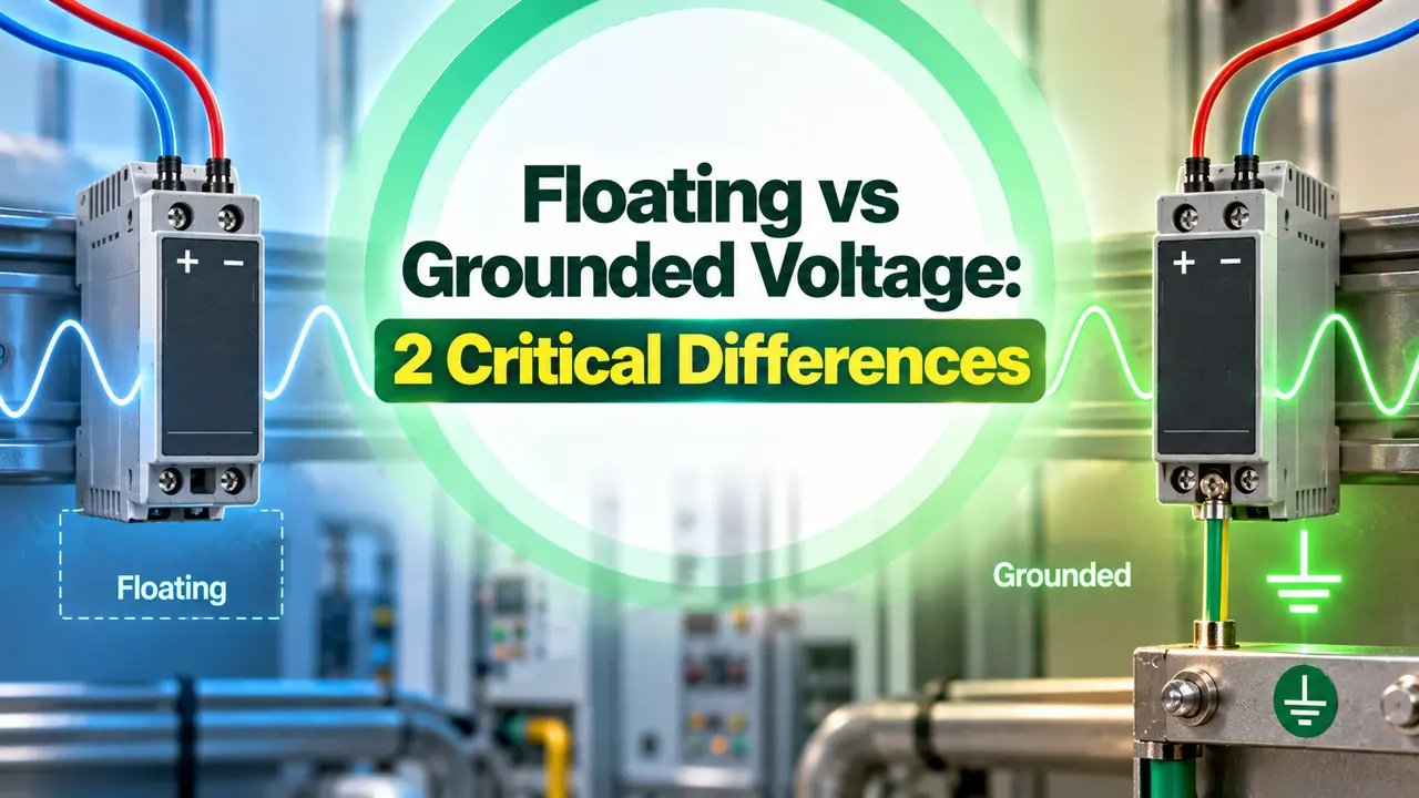
Floating vs Grounded Voltage comes down to whether a circuit's reference point is tied to earth or left free to sit at whatever potential the circuit settles at on its own.
We will cover earth ground versus chassis ground, the safety function grounding actually serves, how ground loops form, and how to choose between a grounded and a floating power supply for a specific job.
What "Ground" Actually Means as a Voltage Reference
Voltage is never a property of a single point. It is always measured between two points, one at a higher potential and one treated as the reference, usually called zero.
That reference point is commonly tied directly to the earth itself, which is why it gets called ground or earth ground. The planet is treated as an effectively infinite reservoir that can absorb or supply electrons without its own potential changing measurably.
Once a system has a solid, stable reference, every other voltage in that system can be stated meaningfully. Without one, a stated voltage value has no fixed meaning at all.
Earth Ground vs Chassis Ground
These two terms get used almost interchangeably in casual conversation, but they describe two genuinely different things.
| Term | What It Means | Key Point |
|---|---|---|
| Earth Ground | An actual physical connection to the earth, typically driven rods several feet into the soil | The true zero reference point in an electrical system |
| Chassis Ground | A reference point on an equipment's metal enclosure | May or may not actually sit at earth potential |
A chassis ground that is properly bonded back to earth sits at the same potential as true earth ground.
A chassis ground that has lost that bond, or never had one, is free to sit at some other potential entirely, which is exactly the floating condition this article is about.
What Makes a Circuit "Floating"
A circuit is described as floating when its reference point, its own internal zero, is not tied to earth ground at all.
That floating reference is not fixed at zero relative to true earth. It can sit anywhere, driven by leakage currents, capacitive coupling from nearby wiring, or whatever imbalance exists in the circuit around it.
This is not a flaw by itself. A genuinely isolated, well designed floating supply is a deliberate and useful engineering choice in the right application, covered further down in this article.
Why Grounding Exists: The Safety Function
The primary reason grounding exists at all is safety, not measurement convenience. A properly grounded system gives fault current a deliberate, low impedance path back to earth.
That low impedance path matters because it decides who, or what, carries a fault current when something goes wrong. With a solid ground path, a fault trips a breaker or blows a fuse quickly, well before a person becomes part of that current path instead.
A floating circuit does not have that same defined path. If insulation fails somewhere in a floating system, there is no guaranteed low impedance route for the fault current to follow, which is the core safety tradeoff floating designs carry.
How Floating Circuits Create Their Own Risk
Floating does not mean immune to shock hazards, it just moves the hazard somewhere less obvious.
This is exactly why a genuinely floating design is treated as a deliberate engineering decision with its own safety analysis, not a shortcut around grounding requirements.
Ground Loops: What Happens When "Ground" Is Not Actually One Potential
In a real installation, every point tied to ground is not actually sitting at exactly the same potential. Conductor length, soil resistance, and distance between grounding points all introduce small differences.
Those small potential differences drive a current between two ground points that should, in theory, be identical, and that current is what forms a ground loop.
A small ground loop mostly shows up as noise, sometimes interrupting communication on a data line such as RS232. A large one can damage equipment outright or introduce a genuine safety hazard.
The full mechanism, along with practical isolation methods, is covered in ground loop causes and prevention.
A properly isolated floating circuit can actually help here, since isolating a system from a shared ground reference removes it from that ground loop path entirely, trading away grounding's safety benefit for immunity to this specific noise source.
Measuring a Floating Circuit Without Being Fooled by It
A floating conductor can read a real sounding voltage on a meter even when no genuine load current is present, a phenomenon technicians call ghost voltage or phantom voltage.
An old style analog meter, or a modern low impedance meter, tends to load that floating conductor down enough that a ghost voltage collapses toward zero on the display, which is why older troubleshooting habits rarely flagged the problem.
A modern high impedance digital multimeter barely loads the circuit at all, so it can display a full, misleading voltage on a conductor that is actually floating and carries no real capacity to do work.
The practical fix is a simple one. When a reading looks suspicious on a supposedly dead or floating conductor, load it briefly with a known resistance, a solenoid tester or a small resistive load, and watch whether the reading collapses.
A genuine source holds its voltage under that load. A ghost voltage does not, and that single check is often enough to tell the two apart in the field.
Real World Situations Where This Distinction Matters
A few everyday scenarios make the floating versus grounded distinction concrete rather than theoretical.
Each of these cases is really the same underlying tradeoff from earlier in this article, applied to a specific, recognizable situation rather than an abstract circuit diagram.
None of these examples argue that one design is always better. A hospital does not ground a patient circuit to save money, and a factory floor does not float its control panels for the sake of noise immunity alone.
The environment and the consequence of a fault decide which tradeoff is worth making, and that decision is usually made once, early, by whoever designs the system rather than left to a technician in the field.
Choosing Between a Grounded and a Floating Power Supply
Negative terminal tied to ground, sits at 0 V
Positive terminal sits at plus 24 V relative to that fixed 0 V reference
Floating 24 VDC example
Neither terminal tied to ground
The 24 V difference between terminals stays fixed, but both terminals can drift together relative to true earth
Predictable fault clearing, lower fault impedance, and straightforward compliance with electrical safety codes. Common in industrial automation, robotics, and compact panel builds.
Immune to ground loop noise and useful where isolation matters most. Common in test and measurement equipment, audio systems, and isolated medical circuits, but needs its own secondary protection.
Neither option is universally correct. The right choice depends on whether the bigger risk in that specific installation is a fault current with no clear path, or a noisy, unreliable signal caused by a ground loop that a floating design would have avoided.
Watch: Floating Ground and Floating Voltage Explained
Floating vs Grounded Voltage Questions Engineers Ask
Related Articles on This Site
- Grounding Techniques Explained
- Thermocouple Grounded vs Ungrounded Junction
- What Is Electromagnetic Interference, EMI
- Shielded Cable and Twisted Pair
- Noise Reduction Techniques for Digital ICs
External References
What We Learn Today
- Floating vs Grounded Voltage is really about where a circuit's reference point sits, tied to earth or left free to drift.
- Grounding exists mainly for safety, giving fault current a defined low impedance path back to earth.
- A floating design trades that safety path away in exchange for immunity to ground loop noise.