
A flow rate tells you how fast product is moving, but the plant bill, the batch recipe and the tanker receipt all depend on how much has actually passed. A well configured totalizer turns every pulse or milliamp into a trusted running volume.
Every flow meter tells you a rate, yet billing, batching and stock control need the accumulated quantity. A flow totalizer integrates that rate over time, and correct K factor scaling decides whether the total can be trusted.
What Is a Flow Totalizer?
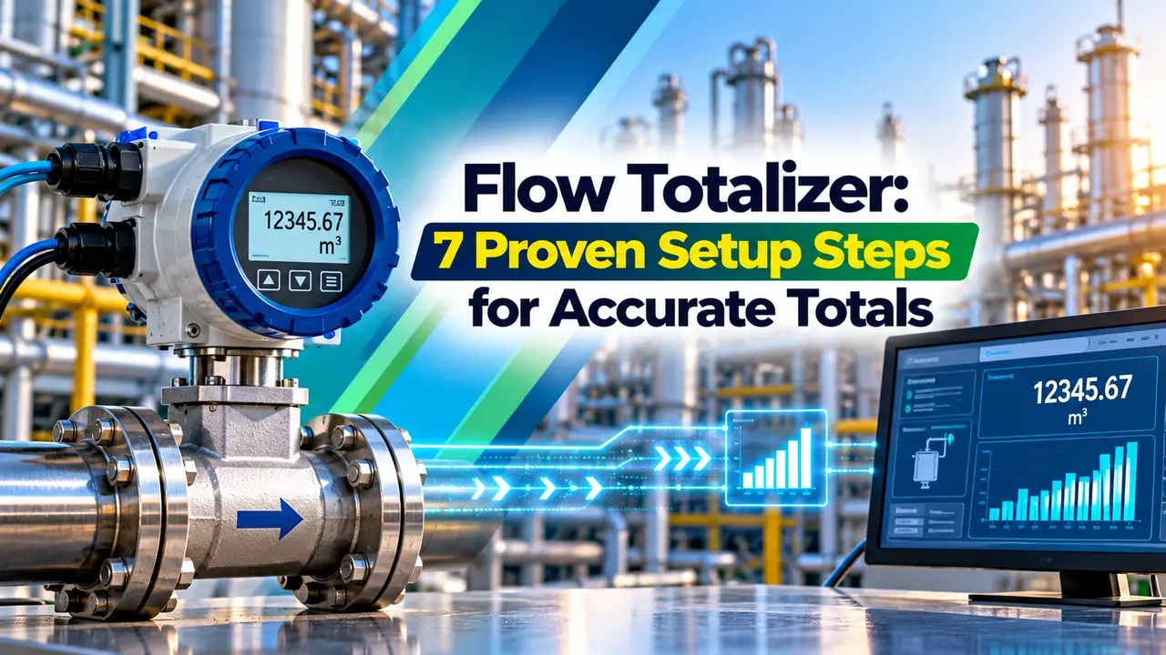
A flow totalizer is an instrument or software function that adds up the quantity of fluid passing a meter over time and shows it as a running total in litres, cubic metres, kilograms or barrels. It usually sits next to a turbine flow meter, a magnetic meter or a Coriolis meter and displays both the rate and the accumulated volume.
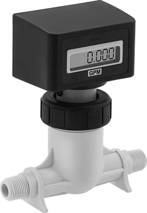
Older meters used a mechanical gear register, much like a household water meter, while modern units are electronic. You will also find the same function inside smart transmitters, PLCs, DCS blocks and the flow computer used for gas and oil metering.
How a Flow Totalizer Works
The working principle is integration: total equals the sum of flow rate multiplied by time. With a pulse input, every pulse already represents a fixed volume, so the instrument simply counts pulses and divides by the K factor.
With an analog input the flow totalizer first converts current into rate, then multiplies by the sampling interval and adds the result every cycle. If the transmitter sends a differential pressure signal, the totalizer must apply square root extraction before integrating, or the total will be badly wrong at low flow.
Control.com author Shawn Dietrich describes a small rotor sensor whose datasheet gives F = 7.5 × Q, which produces 225 Hz at 30 litres per minute. He notes that a PLC with a 4 ms scan time cannot reliably catch such pulses on a normal input, so fast pulses need a hardware counter.
A pulse input flow totalizer is naturally more accurate than an analog one, because each pulse is an exact slice of volume. An analog input adds conversion error at the transmitter, the cable and the input card before integration even starts.
Types of Flow Totalizer Devices
Gear train on the meter drives a number wheel counter.
Panel or field unit counts pulses and scales them with a K factor.
Integrates a 4 to 20 mA rate signal over time.
Meter electronics keep several totals internally.
Software integrates the rate or counts pulses.
Adds pressure and temperature compensation and audit logs.
Positive displacement and turbine meters naturally produce pulses, so a positive displacement flow meter paired with a pulse totalizer is a classic fuel and oil combination. Magnetic and Coriolis meters offer a scaled pulse output as well as a current output, so you can choose either path.
For a PLC based solution, the pulse wire goes to a high speed counter channel rather than a standard digital input. Slow pulses below a few hertz can still use ordinary CTU and CTD counter instructions without missing counts.
K Factor and Scaling Formula
The K factor is the number of pulses a meter produces for one unit of volume, for example 50 pulses per litre. It comes from the meter calibration certificate, and the method of deriving it is covered in flow meter K factor calculations.
Flow rate per second = Frequency ÷ K factor
Rate per hour = Frequency ÷ K × 3600
Example:
K = 50 pulses per litre, count = 1250000 pulses, frequency = 400 Hz
Total = 1250000 ÷ 50 = 25000 L = 25.000 m³
Rate = 400 ÷ 50 = 8 L per second
Rate = 8 × 3600 ÷ 1000 = 28.80 m³/h
Yokogawa states in its YPP6300 datasheet that the field programmable K factor can be set anywhere from 0.00001 to 999,999 pulses per unit. That wide range lets one flow totalizer model serve a tiny dosing meter and a large pipeline turbine meter.
Flow Totalizer Calculator
Always copy the K factor from the latest calibration certificate, not from the catalogue nominal value. Industrial Monitor Direct notes that actual K factors can differ from nominal by 1 to 3 percent, which is a big error on a billing meter.
Second Worked Example: 4 to 20 mA Input
Suppose a magnetic meter is ranged 0 to 50 m³/h on a 4 to 20 mA signal and reads a steady 12 mA. The rate is (12 minus 4) ÷ 16 × 50 = 25 m³/h, so in 2 hours the analog flow totalizer adds 25 × 2 = 50 m³.
If the same input drifts by just 0.1 mA, the rate error is 0.1 ÷ 16 × 50 = 0.31 m³/h, which grows to about 7.5 m³ per day. This is why the raw count to engineering unit conversion in PLC analog scaling must be checked during loop testing.
Resettable and Non Resettable Totals
| Total Type | Who Can Reset | Typical Use |
|---|---|---|
| Resettable total | Operator, push button or remote contact | Shift, batch or daily quantity |
| Non resettable grand total | Nobody, or only with password | Lifetime audit and billing |
| Batch total | Automatic at each batch start | Filling and dosing |
| Forward and reverse totals | Configured per direction | Bidirectional lines |
| Net total | Calculated as forward minus reverse | Tank transfer balance |
A good flow totalizer keeps at least two registers: a resettable total for daily work and a grand total that cannot be cleared from the front panel. The grand total is your audit trail when someone questions a delivery.
Many electronic totalizers save the running total to non volatile memory, so a power cut does not erase the count. Older battery backed units lose the total if the backup cell is flat, which is a common complaint on remote skids.
7 Proven Steps to Set Up a Flow Totalizer
Step seven is the one most often skipped, yet it catches wrong units and wrong decimal points immediately. A simple bucket and stopwatch test on small lines or a wet calibration on larger meters gives real confidence.
Rollover, Overflow and Display Resolution
A six digit display counts to 999,999 and then rolls over to zero. At 28.8 m³/h with a resolution of 1 litre, that six digit counter fills in about 34.7 hours, so a daily report would be wrong every second day.
Yokogawa specifies a total overflow feature up to 999,999,999, after which the register rolls over. In a PLC or DCS, use a double integer or a floating point pair and handle rollover in logic, as the classic digital counter does when it wraps around.
Choose the total unit so the display needs at least one week before it rolls over. If the plant reads totals once a shift, cubic metres with one decimal usually beats litres with no decimal.
Batch Control With a Flow Totalizer
In batching, the flow totalizer counts up from zero and closes a valve when the preset is reached. The same idea is formalised for recipe plants in ISA 88 batch control, where the totalizer becomes a phase in the procedure.
Custody Transfer and Compensation
When a flow totalizer reading becomes an invoice, the system falls under custody transfer rules and legal metrology approval. In India that means Legal Metrology approval of the meter and totalizer, sealing of the configuration and periodic verification.
- Gives the real quantity for billing and stock.
- Enables simple batch and dosing control.
- Works with almost every meter output.
- Keeps an audit trail through the grand total.
- Error builds up over time if scaling is wrong.
- Analog inputs integrate zero offset and drift.
- Low resolution causes early rollover.
- Basic units lack pressure and temperature compensation.
Troubleshooting a Wrong Flow Totalizer Reading
- Confirm K factor and units match the calibration certificate.
- Check pulse type and pull up resistor for NPN outputs.
- Verify input frequency limit is above the maximum meter frequency.
- Look for noise pulses from VFD cables on a scope.
- Check low flow cut off and zero when the pump is stopped.
- Confirm square root is applied once, not twice, on DP meters.
- Compare totals against a tank dip or weighbridge.
Double counting on a flow totalizer usually comes from noise or contact bounce, while low totals usually mean missed pulses. Use shielded twisted pair cable, ground the shield at one end and keep signal cables away from power, as advised for magnetic flow meter installations.
Where Flow Totalizers Are Used
Yokogawa Rate Totalizer Datasheet
K Factor Setup Video
Flow Totalizer FAQ
It is a device or software function that adds up the quantity of fluid passing a meter and shows the running total. A flow totalizer usually displays the instantaneous flow rate as well, either on the same screen or on a second line.
Totals are shown in litres, cubic metres, kilograms or barrels. They are used for billing, batching, stock control and daily plant reports.
It counts every pulse from the meter and divides the count by the K factor. A meter with 50 pulses per litre that sends 1250000 pulses has passed 25000 litres.
The rate is found by dividing the frequency by the same K factor. At 400 Hz the example meter shows 8 litres per second, or 28.8 cubic metres per hour.
Take it from the calibration certificate supplied with the meter, not from the catalogue. Industrial Monitor Direct notes that real K factors can differ from nominal by 1 to 3 percent.
Recheck the value after every recalibration or rotor replacement. Enter it with the correct volume unit, because pulses per gallon and pulses per litre differ by a factor of about 3.785.
A resettable total can be cleared by the operator for each shift, day or batch. It shows the quantity for that period only.
A grand total keeps counting for the life of the instrument and is protected by a password or seal. It acts as the audit trail when a delivery or bill is questioned.
An analog input integrates any small zero offset, so a few microamps above 4 mA add volume all day. Noise pulses on a pulse input cause the same effect.
Set a low flow cut off and check the transmitter zero with the line full and still. Also route signal cables away from motor and VFD power cables.
Rollover happens when the display reaches its largest number and returns to zero. A six digit flow totalizer display rolls over after 999,999 units, for example litres.
Choose a larger unit or fewer decimals so rollover takes at least a week. In PLC logic, use a double integer or floating point pair and handle the wrap around in code.
Usually not, because billing meters need legal metrology approval, sealing and often pressure and temperature compensation. Gas totals must also be corrected from actual to standard conditions before any invoice is raised.
Plants therefore use an approved flow computer with an audit log. A basic flow totalizer remains fine for internal reporting, chemical dosing, utility monitoring and similar plant work.
Related Articles
- Flow Meter K Factor Calculations
- Flow Computer Working Principle
- Turbine Flow Meter Working Principle
- PLC High Speed Counter and Encoder
- What Is Custody Transfer
External References
- YPP6200 and YPP6300 Flow Rate and Totalizer Datasheet, Yokogawa
- Developing a Flow Totalizer Function on a PLC, Control.com
- Flow Measurement, Wikipedia
What We Learn Today
- A flow totalizer integrates flow rate over time, and with a pulse input the total is simply the pulse count divided by the K factor.
- Analog 4 to 20 mA totalizing needs a low flow cut off, because a small zero offset keeps adding volume when the line is stopped.
- Keep a protected grand total, choose units that delay rollover, and verify the K factor against a tank dip, weighbridge or prover.
