
The aluminium electrolytic capacitor is usually the first part to wear out in a power supply, LED driver or drive. A simple temperature based calculation tells you how many years it will really last and what to change when that is not enough.
Every aluminium electrolytic capacitor slowly dries out, and heat decides how fast that happens. This guide shows how to estimate electrolytic capacitor lifetime from the datasheet hours, the real core temperature and the ripple current.
What Is Electrolytic Capacitor Lifetime?
Electrolytic capacitor lifetime is the number of operating hours an aluminium electrolytic capacitor can run before its capacitance, loss factor or leakage drifts outside the limits set by the manufacturer. Unlike a resistor, it wears out by design, because its liquid electrolyte slowly escapes through the rubber seal.
Nippon Chemi Con explains that this diffusion through the seal lowers capacitance and raises tan δ, the loss factor. As the electrolyte dries, the equivalent series resistance rises, the part runs hotter and the ageing speeds up further.
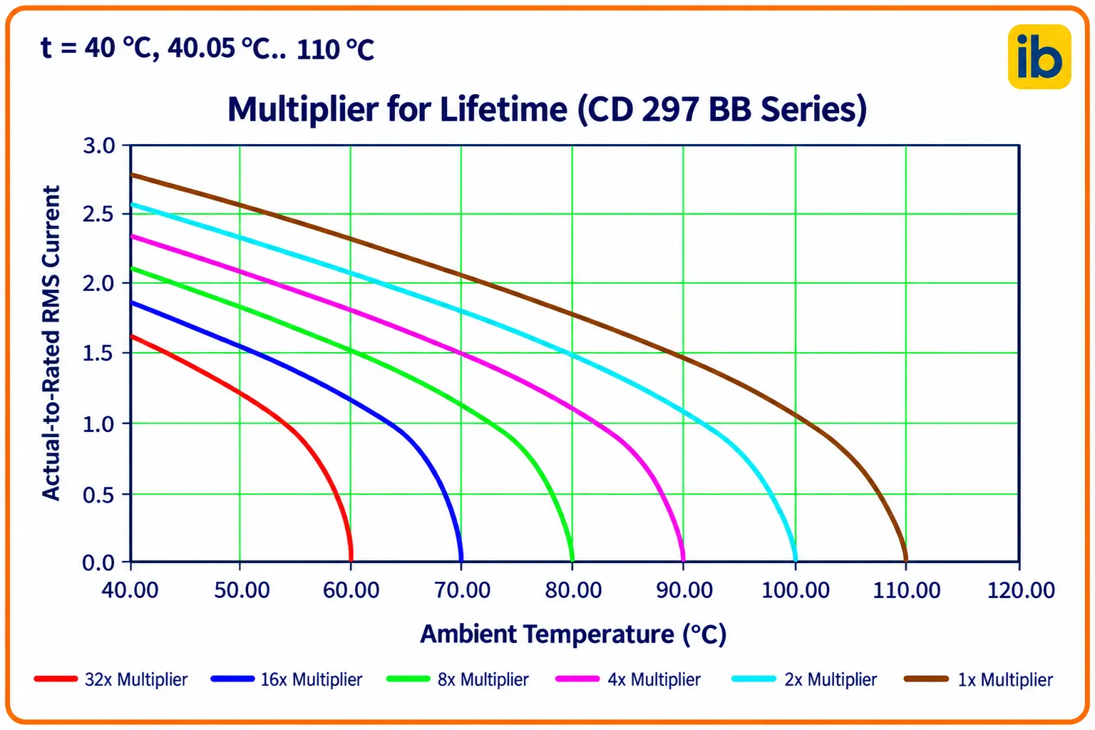
That is why a power supply that worked perfectly for years can suddenly show hum, reboots or ripple on the output. The chart above shows how the life multiplier grows quickly as the temperature and ripple current fall, which is the whole idea behind this article.
How Manufacturers Rate the Endurance Hours
Datasheets state an endurance figure such as 2000 hours at 105 °C, measured with rated voltage and rated ripple current applied. Analog Devices engineer Mark Fortunato notes that these endurance ratings typically run from 1000 to 10000 hours at maximum temperatures of 85 °C or 105 °C.
Two thousand hours is less than three months of continuous running, which shocks many students. The good news is that very few circuits run their capacitors at the full rated temperature, so the real electrolytic capacitor lifetime is much longer.
End of life is defined by limits, not by an explosion. A common set is capacitance change within about 20 percent of the initial value, tan δ no more than twice the specified value and leakage current within the specified value, though each series lists its own numbers.
Würth Elektronik notes that a polymer capacitor gains ten times the life for every 20 °C reduction, instead of two times per 10 °C. Below about 95 °C, a polymer part can outlast a liquid electrolytic part with the same 2000 hour rating.
The 10 °C Rule and the Arrhenius Equation
The electrolyte loss is a chemical and diffusion process, and its rate follows the Arrhenius law. For practical work, it reduces to a simple rule: electrolytic capacitor lifetime doubles for every 10 °C drop in temperature and halves for every 10 °C rise.
L0 = rated endurance hours at rated temperature T0
Tx = actual core temperature in °C
Tx = ambient temperature + ripple self heating
Example:
L0 = 2000 h, T0 = 105 °C, ambient 55 °C, ripple rise 5 °C
Tx = 55 + 5 = 60 °C
2^((105 minus 60) ÷ 10) = 2^4.5 = 22.63
Lx = 2000 × 22.63 = 45255 h, about 5.2 years
Nippon Chemi Con states that the temperature acceleration factor is generally between 1.7 and 2.3 per 10 °C, so 2 is a reasonable middle value. In its own tests, electrolyte weight loss rose about 1.9 times for each 10 °C step.
The core temperature, not the room temperature, is what matters. Measure or estimate the air right around the can, then add the self heating from ripple current, because a thermocouple taped to the sleeve often reads much higher than the cabinet air.
Chemi Con advises using 40 °C as the lowest ambient in any estimate and capping the result at 15 years. A calculation that gives 60 years only means temperature is no longer the limiting factor.
Ripple Current and Self Heating
Ripple current flows through the ESR and turns into heat, roughly W = I² × ESR. In a rectifier circuit or a buck converter, this internal heating can add several degrees to the core even in a cool cabinet.
Chemi Con explains that the temperature rise grows with the square of the ratio of actual ripple to rated ripple. Running at half the rated ripple therefore gives only one quarter of the rated self heating, which is a strong reason to choose a slightly larger part for longer electrolytic capacitor lifetime.
Ripple ratings are usually stated at 120 Hz, so a correction is needed at switching frequencies. Chemi Con lists a typical multiplier of 1.40 at 10 kHz for 100 to 1000 µF parts, which means the same can handles more ripple at higher frequency.
| Factor | Effect on Life | What to Check |
|---|---|---|
| Core temperature | Doubles per 10 °C cooler | Ambient plus ripple rise |
| Ripple current | Heat grows with current squared | Actual RMS against rating |
| Ripple frequency | Higher frequency allows more current | Frequency multiplier table |
| Applied voltage | Small for most parts below rating | Series specific voltage factor |
| Airflow and mounting | Cooler can, longer life | Spacing from heat sinks |
Does Voltage Derating Extend Life?
Here the manufacturers disagree, so always read the series datasheet. Nippon Chemi Con states that at or below rated voltage the voltage factor is 1, so running at lower voltage gives little extra life for most of its parts.
Other makers do publish a voltage multiplier. A DigiKey engineering article on a Cornell Dubilier part uses Mv = 4.3 minus 3.3 × (Va ÷ Vr), which gives about 1.37 at 400 V on a 450 V rating.
Either way, the practical rule is to keep the peak of DC plus ripple below the rated voltage and never apply reverse voltage.
Chemi Con warns that even about 1 V reverse can reduce capacitance. A Zener diode or a well designed rectifier stage helps keep surges within limits.
6 Steps to Calculate Electrolytic Capacitor Lifetime
These six steps work for SMPS output filters, LED drivers, UPS DC links and VFD bus capacitors alike. Write down every assumption, because the answer is only as good as the temperature you used.
Electrolytic Capacitor Lifetime Calculator
This electrolytic capacitor lifetime calculator assumes 24 hour running, 8760 hours per year. For a product that runs one shift a day, divide the years by the fraction of the day it is switched on.
Second Worked Example: Cooler Running Doubles Life
Analog Devices gives a real case from LED bulb design. A 2000 hour, 105 °C part running at 100 °C gives 2000 × 2^0.5, which is about 2800 hours, far too short for a lamp.
In the same study, reducing self heating made the chosen 7000 hour, 105 °C part run about 10 °C cooler, which doubled its estimated endurance to around 40000 hours. One better part and a little less heat changed the product from weak to dependable.
Now try a drive cabinet in an Indian summer at 50 °C with 10 °C of ripple rise and a 5000 hour, 105 °C part. The core is 60 °C, so the life is 5000 × 22.63, about 113000 hours, but the 15 year cap applies, which is useful for planning power supply ageing replacements.
A DigiKey worked example estimated about 80000 hours from temperature alone for a 10000 hour, 105 °C part at 75 °C core. Adding full ripple at 360 Hz from a 3 phase rectifier cut the estimate to just over one year.
Electrolytic Capacitor Lifetime Myths
Choosing Capacitors for Long Life
Rated 5000 to 10000 hours, the safe default for SMPS and drives.
Cheaper, but gives only about one quarter of the life of a similar 105 °C part at the same core temperature.
Very low ESR and a gentler temperature curve.
Compare electrolytic capacitor lifetime between datasheets at equal temperature and ripple, not on rated hours alone. The failure modes of electrolytic, ceramic and tantalum capacitors also differ, which matters when you choose a replacement technology.
Place the capacitor away from heat sinks, power resistors and magnetics, since a few centimetres can mean 10 °C. Good cooling fan airflow and thermal vias lower the core temperature directly.
Parallel two smaller capacitors instead of one large can when ripple is high. The ripple splits between them, and the self heating in each part drops sharply because it follows the current squared.
- Shows weak parts before the design is frozen.
- Gives a basis for preventive replacement intervals.
- Uses only datasheet values and a temperature measurement.
- Helps justify a better capacitor series to buyers.
- Ignores surge voltage, inrush and storage effects.
- Assumes a steady temperature over the whole life.
- Differs between manufacturers and series.
- Gives an estimate, not a guarantee for one unit.
Field Checks for Ageing Capacitors
- Measure the case temperature with an IR gun under full load.
- Check output ripple on an oscilloscope against the original value.
- Measure ESR with an ESR meter, compared with the datasheet.
- Look for bulging vents, dried electrolyte or brown residue.
- Confirm the replacement has equal or higher ripple and temperature rating.
- Record the date code and operating hours for trend analysis.
In plants, ageing bus capacitors often show up first as VFD trips or as noisy analog signals from a tired 24 V supply. Planned replacement after the calculated life is cheaper than a sudden shutdown.
Würth Elektronik Lifetime Support Note
Video on How Capacitor Life Is Determined
Electrolytic Capacitor Lifetime FAQ
The usual method multiplies the rated endurance hours by 2 raised to the temperature margin divided by 10. The temperature margin is the rated temperature minus the actual core temperature.
A 2000 hour, 105 °C part at a 60 °C core gives about 45000 hours. Some makers also add separate voltage and ripple factors to this basic estimate.
It is the endurance test result at full rated temperature, voltage and ripple current. After that time the capacitance, loss factor and leakage still stay within the stated end of life limits.
It does not mean the part fails after 2000 hours in your circuit. At lower core temperatures the real life is many times longer.
The electrolyte slowly escapes through the rubber seal, and this process speeds up with heat. Chemi Con measured about 1.9 times faster electrolyte loss for each 10 °C rise.
So a capacitor running 20 °C cooler lasts roughly four times longer. Cooling the part is the cheapest way to extend electrolytic capacitor lifetime in any power supply or drive panel.
Ripple current flows through the internal resistance and creates heat inside the can. That extra heat raises the core temperature above the ambient air.
The temperature rise grows with the square of the ripple current. Doubling the ripple therefore gives about four times the self heating and a much shorter service life for the part.
For most Chemi Con parts the voltage factor is 1 at or below rated voltage, so the gain is small. Some makers, including Cornell Dubilier, publish a voltage multiplier that does reward derating.
Always follow the formula in the datasheet for the exact series. Never exceed rated voltage, and avoid any reverse voltage across the part.
Polymer parts follow a 20 °C rule, gaining ten times life for each 20 °C reduction according to Würth Elektronik. At moderate temperatures they usually outlast liquid parts.
They also have much lower internal resistance, which reduces ripple heating. They cost more and are usually available in lower voltage ranges, so check the rating carefully before you swap technologies.
Replace them before the calculated life ends, and sooner if the measured ripple or internal resistance has clearly risen. Bulging vents, brown residue or leaking electrolyte call for immediate replacement of the part.
Record the operating hours and case temperature for each drive or supply. That record turns the electrolytic capacitor lifetime estimate into a practical maintenance plan.
Related Articles
- Capacitor ESR Equivalent Series Resistance
- Electrolytic vs Ceramic vs Tantalum Capacitor Failure Modes
- Capacitor Types Explained
- Power Supply Aging in Automation
- How Decoupling Capacitors Work
External References
- Expected Lifetime of Aluminum Electrolytic and Polymer Capacitors, Würth Elektronik
- Ensure Long Lifetimes from Electrolytic Capacitors, Analog Devices
- Aluminum Electrolytic Capacitor, Wikipedia
What We Learn Today
- Electrolytic capacitor lifetime roughly doubles for every 10 °C drop in core temperature, so the rated hours at 105 °C grow fast in cooler circuits.
- Ripple current heats the capacitor through its ESR, and the self heating rises with the square of the current ratio.
- Chemi Con suggests using at least 40 °C ambient in estimates and capping the calculated life at about 15 years.
