
Resistors are the most common component in any electronic circuit, but choosing the wrong type for an application causes measurement errors, instability, or outright failure. Fixed resistors, variable resistors, and special purpose resistors each have distinct construction, tolerance, temperature behaviour, and frequency response characteristics.
This guide covers every major resistor type used in industrial, instrumentation, and electronics design -- with a series and parallel resistance calculator.
The resistance of a component determines how much current flows for a given voltage -- V = IR (Ohm's Law). The resistor type determines how stable that resistance remains across temperature and frequency.
That stability is what separates a precision measurement circuit from one that drifts over time.
The Role of Resistance in a Circuit
Every resistor limits current, divides voltage, or converts electrical energy to heat. See the Ohm's Law basics guide and the what is resistance article for the underlying theory.
In practice, no resistor maintains exactly its marked value under all conditions. Temperature, frequency, and long term use all shift the resistance slightly.
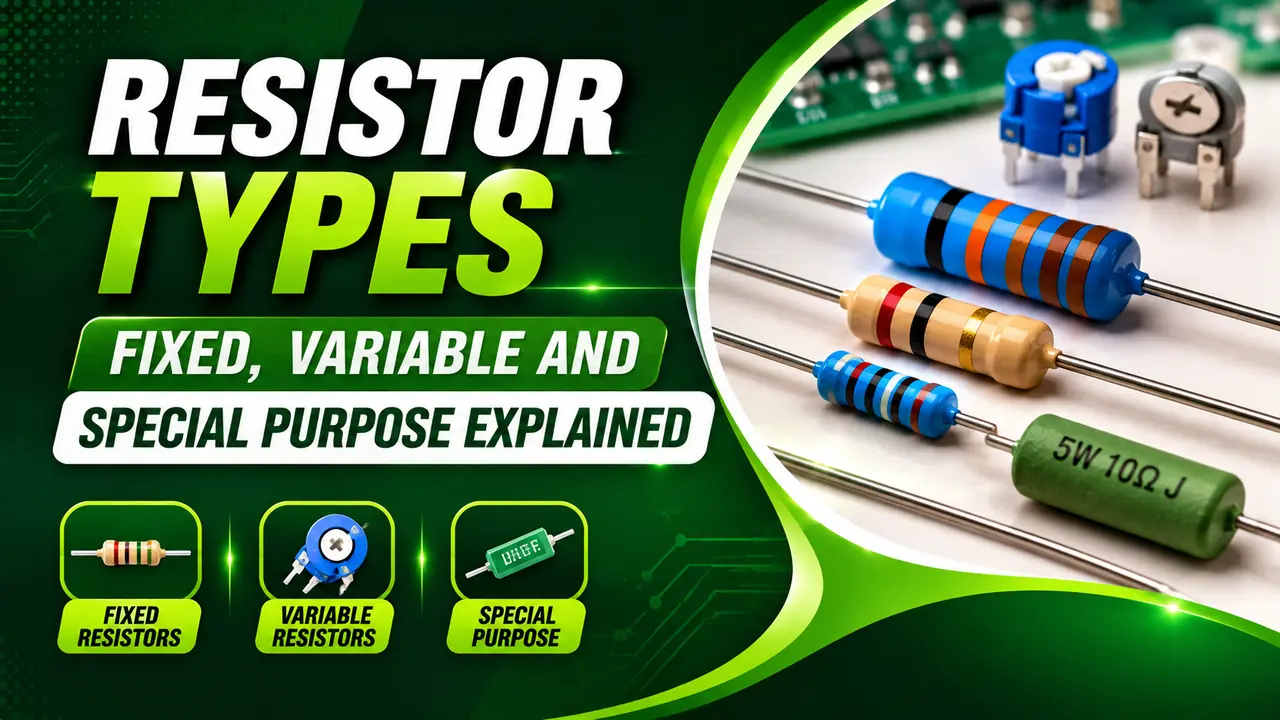
The type and construction of the resistor determines how large these effects are and whether they matter for the application.
Fixed Resistors: Types and When to Use Each
Fixed resistors have a resistance value set during manufacture and unchanged in normal use. The construction material determines the tolerance, temperature coefficient (TC), noise, and frequency response.
Carbon Film Resistor
A thin carbon film deposited on a ceramic rod, with a helical cut to set the value. Low cost, general purpose.
Tolerance: ±5% typical. TC: minus 200 to minus 500 ppm/°C. Noise is higher than metal film. Suitable for non critical circuits, pull-up and pull-down networks, and basic signal conditioning where precision is not required.
General purpose, low costMetal Film Resistor
A thin nichrome or tin oxide film on a ceramic substrate. Industry standard for precision work. Tolerance: ±1% to ±0.01%. TC: 5 to 50 ppm/°C.
Used in signal conditioning circuits, precision voltage dividers, instrumentation amplifiers, and any circuit where temperature drift matters. The E96 series covers 96 values per decade to allow close matching.
Precision, low noiseWirewound Resistor
Resistance wire (usually nichrome) wound on a ceramic or fiberglass former. Handles high power -- 5 W to several kilowatts. TC can be very low for precision types.
Used in power supplies, load banks, motor braking resistors, and precision bridge circuits. The wound construction creates significant inductance, making wirewound resistors unsuitable for high frequency or RF circuits. Used in Wheatstone bridge applications where power and accuracy both matter.
High power, high precisionThick and Thin Film Resistors (SMD)
Surface mount resistors in 0402, 0603, 0805, and 1206 packages. Thick film: ±1 to 5%, 100 to 200 ppm/°C. Thin film: ±0.1%, 10 to 25 ppm/°C.
Used on all modern PCBs. Thin film SMD types offer near metal film performance in a tiny package. See PCB design fundamentals and PCB design rules for placement guidance.
SMD, compact, PCB standardCarbon Composition Resistor
Ground carbon mixed with a binding material and moulded into a cylinder. Oldest type, now mostly obsolete. Tolerance: ±5 to 20%. Very high noise, high TC (minus 900 ppm/°C), susceptible to moisture absorption.
Still found in legacy equipment and vintage audio circuits where their particular noise characteristics are considered desirable. Not recommended for new designs.
Legacy, high noiseCurrent Sense (Shunt) Resistor
Very low resistance (milliohm range), high power rating, ultra-low TC (typically 5 to 20 ppm/°C). Placed in series with a circuit to measure current by measuring the small voltage drop across it.
Used in motor drives, battery management systems, and industrial instrumentation. See the detailed shunt resistors in instrumentation guide. The voltage across the shunt is amplified by an instrumentation amplifier in the signal conditioning stage.
Current measurementVariable Resistors: Potentiometers, Rheostats and Trimmers
Variable resistors allow the resistance to be adjusted mechanically or electrically. The three main types serve different purposes in circuit design and instrumentation.
| Type | Connections Used | Circuit Function | Typical Application |
|---|---|---|---|
| Potentiometer | All three terminals -- two ends and the wiper | Voltage divider -- output voltage varies proportionally with wiper position | Audio volume control, position sensing, manual setpoint adjustment in older process controllers |
| Rheostat | One end and the wiper only | Variable series resistance -- limits current | Motor speed control (older), lamp dimming, heating element adjustment |
| Trimmer (preset) | All three terminals, adjusted with a screwdriver | Fine calibration adjustment -- set once, not changed in normal operation | Offset and gain trim in op amp circuits, calibration of transmitters, threshold adjustment in comparators |
| Digital potentiometer | Controlled by SPI or I2C signal | Software controlled voltage division or resistance -- replaces mechanical pot in digital designs | Programmable gain amplifiers, automatic calibration systems, IoT sensor nodes |
Special Purpose Resistors
Thermistor (NTC and PTC)
A resistor whose value changes dramatically with temperature.
NTC (Negative Temperature Coefficient) resistance falls as temperature rises -- used for temperature sensing and inrush limiting. PTC (Positive Temperature Coefficient) resistance rises sharply above a threshold -- used as self-resetting fuses and motor winding protection.
NTC thermistors are used in temperature transmitters as the sensing element. Their high sensitivity (4 to 5% per °C) gives better resolution than an RTD but requires linearisation.
Compare with RTD behaviour in the RTD resistance calculator.
Temperature sensingLight Dependent Resistor (LDR / Photoresistor)
Resistance falls with increasing light intensity. Made from cadmium sulphide (CdS). Resistance can range from megaohms in darkness to tens of ohms in bright light.
Used in automatic street lighting controls, light activated alarms, and ambient light compensation circuits. Slow response time (tens of milliseconds) makes LDRs unsuitable for fast optical sensing. See the dedicated LDR working principle guide for construction details and circuit examples.
Light sensingVaristor (VDR / MOV)
A voltage-dependent resistor. Resistance stays high under normal voltage, then drops sharply (conducting heavily) when voltage exceeds the clamp threshold. Metal Oxide Varistors (MOVs) are the most common type.
Used for transient surge protection on power supply inputs, signal line protection in field instruments, and lightning protection on outdoor cable runs. The noise reduction and transient protection guide covers MOV selection and placement on PCBs.
Surge protectionFusible Resistor
Combines the function of a resistor and a fuse. Burns open safely under overload conditions to protect the circuit, without the explosive failure mode of some wirewound types.
Used in power supply circuits and battery charger protection stages where a single component must perform both current limiting and fault protection simultaneously. The open-circuit failure mode is intentional and safe.
Overcurrent protectionPull Up and Pull Down Resistors
Standard fixed resistors (typically 1 kΩ to 100 kΩ) connected to a supply rail or ground to define the logic state of a signal line when no active driver is present. Not a special construction -- a special application of standard resistors.
Used on every open-collector output, open-drain GPIO, and I2C bus line. See digital logic gates and noise reduction in digital ICs for how pull-up values affect signal integrity and bus speed.
Logic level definitionTermination Resistor
Matched to the characteristic impedance of a transmission line (typically 50 Ω, 75 Ω, or 120 Ω) to prevent signal reflections on long cable runs. Must match the cable impedance precisely.
Used at both ends of RS-485 networks, CAN bus lines, and high speed differential pairs. Incorrect termination causes reflections that corrupt data at higher baud rates.
The 120 Ω requirement for RS-485 and 75 Ω for ControlNet are both critical for reliable communication.
Signal integrityResistor Formulas: Series, Parallel and Divider
R_parallel = 1 / (1/R₁ + 1/R₂ + 1/R₃ + ...)
For two resistors: R_parallel = (R₁ × R₂) / (R₁ + R₂)
Parallel: voltage is the same across all resistors. Equivalent is always less than the smallest.
Voltage Divider: V_out = V_in × R₂ / (R₁ + R₂)
R₁ connects V_in to V_out. R₂ connects V_out to ground.
Resistor Calculator
Choosing the Right Resistor: Comparison Table
| Resistor Type | Tolerance | TC (ppm/°C) | Power | Best Use |
|---|---|---|---|---|
| Carbon film | ±5% | minus 200 to minus 500 | 0.125 to 0.5 W | Pull up, pull-down, non critical bias |
| Metal film | ±0.1 to 1% | 5 to 50 | 0.125 to 0.6 W | Precision voltage dividers, instrumentation |
| Wirewound | ±0.01 to 1% | 1 to 20 | 5 W to several kW | Power dissipation, precision bridges |
| Thick film SMD | ±1 to 5% | 100 to 200 | 0.063 to 0.5 W | General PCB circuits |
| Thin film SMD | ±0.1 to 0.5% | 10 to 25 | 0.063 to 0.25 W | Precision PCB circuits, DAC reference dividers |
| Shunt (current sense) | ±0.1 to 1% | 5 to 20 | 1 to 10 W | Current measurement in power circuits |
| NTC Thermistor | ±1 to 3% | minus 3000 to minus 5000 | 0.1 to 0.5 W | Temperature sensing, inrush limiting |
| LDR | ±20 to 30% | Variable with illumination | 0.1 to 0.5 W | Light detection, ambient sensing |
| Varistor (MOV) | Clamp voltage ±10% | Not rated for steady operation | Joules (surge energy) | Transient surge suppression |
Watch: Resistor Types Explained
Resistor Type Questions
External References
What We Learn Today
- Metal film resistors are the standard choice for precision circuits -- ±1% tolerance, TC 5 to 50 ppm/°C
- Wirewound resistors handle high power but are inductive -- unsuitable for high frequency circuits
- NTC thermistors fall in resistance with temperature (high sensitivity); PTC types rise sharply at a threshold
- Shunt resistors (milliohm range) measure current by the voltage drop across them in series with the circuit
- R_series = R₁ + R₂; R_parallel = (R₁ × R₂) / (R₁ + R₂); V_out = V_in × R₂ / (R₁ + R₂)
- Voltage divider output is only accurate when load resistance is at least 10 times larger than the lower resistor