
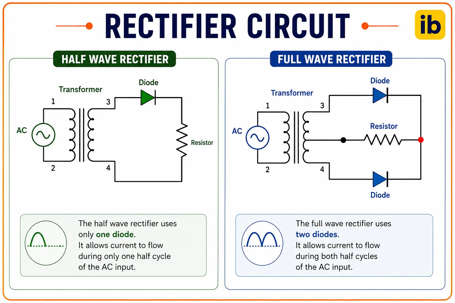
A diode rectifier circuit converts AC voltage to pulsating DC by using the one-way conducting property of diodes. Half wave rectifiers use one diode and pass only one half of the AC cycle. Full wave rectifiers use two or four diodes and pass both halves.
This guide covers all three diode rectifier types with waveforms, formulas, worked examples, and a live output voltage calculator.
A diode rectifier circuit produces pulsating DC. The average output voltage depends on the peak input voltage and the rectifier type: 0.318 × Vpeak for half wave, 0.636 × Vpeak for full wave. A filter capacitor smooths the ripple to usable DC.
Diode Rectifier Circuit: How Diodes Convert AC to DC
A diode conducts current in only one direction. When AC voltage drives a diode forward, current flows. When the AC reverses, the diode blocks. This selective conduction is what turns alternating current into pulsating direct current.
Three circuit configurations use this property: the half wave rectifier, the centre tap full wave rectifier, and the bridge rectifier. Each trades circuit complexity for better DC output. Click any term to expand.
Three Diode Rectifier Circuit Types
1. Half Wave Rectifier
The simplest diode rectifier circuit uses one diode in series with the load. During the positive half cycle, the diode conducts; during the negative half, it blocks and output is zero.
Only half the available AC power reaches the load.
Vpeak: peak value of the AC input (Vrms × √2)
Vrms: RMS supply voltage (e.g. 230 V from mains)
Efficiency: 40.6% -- less than half the input power reaches the load
Ripple frequency: equals the supply frequency (50 Hz or 60 Hz)
The output has large gaps at mains frequency. A smoothing capacitor reduces ripple but a half wave diode rectifier needs a much larger capacitor than a full wave design for equivalent ripple.
See the capacitor types guide for electrolytic capacitor selection.
2. Full Wave Centre Tap Rectifier
Two diodes and a centre tapped transformer. The centre tap is connected to the negative output terminal (ground). Each diode conducts on alternate half cycles, so both halves of the AC waveform appear at the output.
Vpeak: peak voltage of each transformer half-secondary
Efficiency: 81.2% -- both half cycles used
Ripple frequency: 2 × supply frequency (100 Hz for 50 Hz mains)
Limitation: each half of the secondary only delivers half the transformer secondary voltage to the load
The centre tap doubles ripple to 100 Hz, improving smoothing. Each diode must withstand the full secondary voltage in reverse -- a key limitation.
3. Full Wave Bridge Rectifier
Four diodes in a bridge arrangement. No centre tapped transformer required. During the positive half cycle, D1 and D3 conduct; during the negative half cycle, D2 and D4 conduct. In both cases, current flows through the load in the same direction.
Vpeak: peak secondary voltage of the transformer
VF: forward voltage drop per diode (typically 0.7 V for silicon, 0.3 V for Schottky)
Two diodes conduct simultaneously, so subtract 2 × VF from the output
Ripple frequency: 2 × supply frequency (100 Hz for 50 Hz mains)
Efficiency: 81.2% (same as centre tap, but with two-diode voltage drop)
Rectifier Output Voltage Calculator
Half Wave vs Full Wave Diode Rectifier: Comparison
| Parameter | Half Wave | Full Wave Centre Tap | Bridge Rectifier |
|---|---|---|---|
| Diodes required | 1 | 2 | 4 |
| Transformer | Standard | Centre-tapped (more expensive) | Standard |
| Average Vdc | 0.318 × Vpeak | 0.636 × Vpeak | 0.636 × Vpeak minus 2VF |
| Ripple frequency | 50 Hz (at 50 Hz mains) | 100 Hz | 100 Hz |
| Efficiency | 40.6% | 81.2% | 81.2% (minus diode losses) |
| Smoothing difficulty | Hard -- large capacitor needed | Easier -- higher ripple frequency | Easiest -- 100 Hz ripple, no transformer penalty |
| PIV per diode | Vpeak | 2 × Vpeak | Vpeak |
| Best for | Very low power, simple signal detectors | Medium power where centre tap available | All general purpose power supplies |
Rectifier Circuit Applications
Mains Power Supply
Bridge rectifiers are standard in AC to DC power supplies. The mains transformer steps down voltage; the bridge rectifier converts it to pulsating DC; a filter capacitor smooths the ripple. A voltage regulator (linear or switching) then delivers stable DC. See the transformer guide.
Battery Chargers
Half wave rectifiers are used in simple low-cost battery chargers where ripple is less critical. The pulsating DC directly charges the battery, which itself acts as a filter. For precision charging, a full wave bridge diode rectifier with a regulator circuit is used.
Signal Demodulation
AM radio receivers use a single diode to demodulate the amplitude modulated carrier. An RC filter recovers the audio.
See the diode types guide for Schottky diodes used at radio frequencies.
Instrumentation Power Rails
DCS and PLC enclosures use bridge rectifiers to produce the 24 V DC rail from a small internal transformer.
See the semiconductor guide for diode physics and the RMS value guide for converting RMS to peak voltage.
Watch: Bridge Rectifier vs Half Wave Rectifier Explained
Diode Rectifier Circuit Questions
External References
- Full Wave Rectifier and Bridge Rectifier Theory -- Electronics Tutorials
- Introduction to the Full Bridge Rectifier -- All About Circuits
What We Learn Today
- A diode rectifier circuit converts AC to pulsating DC using the one-way conduction property of diodes
- Half wave: 1 diode, Vdc = 0.318 × Vpeak, 40.6% efficiency, ripple at supply frequency
- Full wave centre tap: 2 diodes + centre tapped transformer, Vdc = 0.636 × Vpeak, ripple at 2× supply frequency
- Bridge rectifier: 4 diodes, no centre tap needed, Vdc = 0.636 × Vpeak minus 2VF, most common type in practice
- Smoothing capacitor fills the gaps between rectified pulses -- larger capacitance gives lower ripple
- Schottky diodes (VF = 0.3 V) reduce conduction losses by more than 50% compared to silicon diodes (VF = 0.7 V)