
Table of Contents
ToggleWhat is Signal Conditioning?
Every sensor in an industrial plant whether it measures temperature, pressure, flow, level or vibration produces a raw electrical signal when it detects a physical change. The problem is that most raw sensor signals are weak, noisy, non-linear, or in the wrong format for the next device in the system.
Signal conditioning solves this. It is the process of manipulating a raw sensor signal to make it clean, strong, and compatible with the control system, data acquisition system or PLC receiving it.
Think of it as a translator and gatekeeper sitting between the sensor and the control system it converts the sensor output into a signal that is accurate, reliable and processable.
Where Does Signal Conditioning Sit in the Instrumentation Chain?
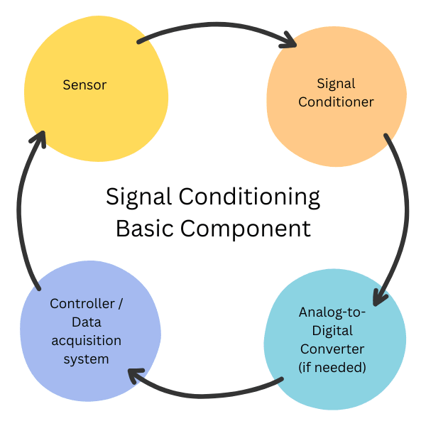
It generally sits between the sensor/transducer and the measurement/control system.
Sensor → Signal Conditioner → Analog-to-Digital Converter (if needed) → Controller / Data acquisition system.

Why Is Signal Conditioning Important?
Without proper signal conditioning, measurement errors can enter the system at the very first step before any control action has even been attempted. Common consequences of missing or poor signal conditioning include:
1. Inaccurate readings: A millivolt thermocouple signal digitised directly without amplification will have far too much quantisation error for reliable temperature control.
2. Noise-corrupted data: Motors, VFDs, and switching devices inject high-frequency electrical noise into signal cables, especially in long runs.
3. Ground loops: Connecting a grounded sensor directly to a grounded controller through a long cable creates a current loop that corrupts the measurement.
4. Incompatible signal formats: A vibration sensor producing a frequency output cannot connect directly to a controller expecting 4-20 mA.
Non-linear output: Sensors like thermocouples have a curved voltage-temperature relationship that must be corrected before the reading is usable.
Types of Signal Conditioning in Instrumentation
There are six main types of signal conditioning functions. A single signal conditioning module may perform one or several of these simultaneously depending on the sensor type.
1. Amplification
Many sensors produce millivolt or microvolt-level output signals far too small for direct digitisation without introducing significant error.
An amplifier boosts these low-level signals to a usable range, typically 0-10 V or 4-20 mA.
The gain of an amplifier is the ratio of output to input voltage. Instrumentation amplifiers are specifically designed for this task because they have high common-mode rejection meaning they amplify the differential signal from the sensor but reject noise that appears equally on both input wires.
2. Filtering
Industrial environments are full of electrical noise from motors, variable frequency drives, contactors, welding equipment, and radio frequency sources. A filter blocks unwanted frequency components while letting the real measurement signal through.
1. Low-pass filters: Allow slow-changing signals (temperature, level) to pass while blocking high-frequency noise above a set cutoff frequency.
2. High-pass filters: Block slow drift and DC offset while allowing faster signals through useful in vibration measurement.
3. Band-pass filters: Allow only a specific frequency range through, used in frequency-output sensors.
4. Notch filters: Remove a single specific frequency, often 50 Hz or 60 Hz mains interference.
3. Isolation
Electrical isolation separates the input side (from the sensor) from the output side (to the controller) so that no direct electrical connection exists between them. This protects both the signal integrity and the equipment from:
1. Ground loops (the most common source of measurement error in instrumentation)
2. High-voltage transients and surges from switching devices
3. Common-mode voltage differences between remote field sensors and control room equipment
Isolation is achieved using optical isolators (optocouplers), isolation transformers, or capacitive coupling inside the module.
4. Linearization
Many sensors do not have a linear relationship between the physical variable they measure and their electrical output. Linearization corrects for this curve so that equal changes in the physical variable produce equal changes in the output signal.
1. Thermocouples: Have a highly non-linear voltage-temperature characteristic. Each thermocouple type (K, J, T, E, etc.) has a different curve that must be compensated.
2. RTDs: Slightly non-linear. The Callendar-Van Dusen equation is used to correct Pt100 and Pt1000 resistance-temperature curves.
3. pH sensors: The Nernst equation gives a non-linear relationship at extreme pH values.
4. Differential pressure flow meters: The relationship between flow rate and differential pressure is a square-root function requiring square-root extraction (a form of linearization).
5. Signal Conversion
Different parts of an instrumentation system often use different signal standards. Signal converters change from one signal type to another without altering the information content. Common conversions include:
From | To | Typical Use Case |
4-20 mA current | 0-10 V voltage | Controller with voltage input only |
Frequency / pulse | 4-20 mA | Turbine flow meter to DCS |
Millivolt (thermocouple) | 4-20 mA | Long-distance temperature transmission |
RTD (resistance) | 4-20 mA | Standard temperature transmitter output |
HART digital | 4-20 mA analogue | Legacy system integration |
0-10 V | 0-5 V or 4-20 mA | System range scaling |
6. Excitation (Bridge Completion)
Some sensors require an external power supply called excitation to produce their output signal. Unlike active sensors that generate their own voltage (like thermocouples), passive sensors need this supplied energy to function. Signal conditioners provide precisely regulated excitation and, where needed, complete the measurement bridge circuit.
1. Strain gauges and load cells: Require a stable excitation voltage (typically 5 V, 10 V or 12 V DC) to the Wheatstone bridge. The conditioner measures the small imbalance voltage that results from physical strain.
2. RTDs: Require a known excitation current (typically 1 mA) passed through the resistance element. The conditioner measures the resulting voltage to calculate resistance.
3. Capacitive pressure sensors: Require an AC excitation signal for the capacitance bridge.
Signal Conditioning Requirements by Sensor Type
Not every sensor needs every type of conditioning. The table below shows which conditioning functions apply to the most common sensor types:
Sensor Type | Amplify | Filter | Isolate | Linearize | Convert | Excite |
Thermocouple | ✔ Yes | ✔ Yes | ✔ Yes | ✔ Yes (CJC) | ✔ Yes | No |
RTD (Pt100/Pt1000) | ✔ Yes | ✔ Yes | ✔ Yes | ✔ Yes | ✔ Yes | ✔ Yes |
Strain Gauge / Load Cell | ✔ Yes | ✔ Yes | ✔ Yes | Partial | ✔ Yes | ✔ Yes |
4-20 mA Transmitter | No | ✔ Yes | ✔ Yes | No | Partial | No |
Piezoelectric (vibration) | ✔ Yes | ✔ Yes | ✔ Yes | No | ✔ Yes | ✔ Yes (IEPE) |
Frequency / Pulse (turbine) | No | Partial | ✔ Yes | No | ✔ Yes | No |
Voltage output (0-10 V) | Partial | ✔ Yes | ✔ Yes | No | ✔ Yes | No |
Active vs Passive Signal Conditioning
Signal conditioning modules are broadly classified as active or passive:
| Active Conditioning | Passive Conditioning |
Power supply | Requires external power to operate | No external power needed |
Gain | Can amplify the signal | Cannot amplify — may attenuate |
Isolation | Can provide galvanic isolation | Limited isolation only |
Cost | Higher — more components | Lower — simple components only |
Examples | Instrumentation amplifiers, isolation amplifiers, transmitters | RC filters, voltage dividers, resistive bridges |
Signal Conditioning vs Smart Transmitter — What Is the Difference?
This is a common point of confusion. A field-mounted smart transmitter (such as a HART pressure transmitter or temperature transmitter) already performs signal conditioning internally it amplifies, linearizes, compensates and converts the raw sensor output to a 4-20 mA loop signal before leaving the instrument.
A separate signal conditioning module is typically used when:
1. The sensor is a simple element (thermocouple, RTD, strain gauge) without built-in electronics
2. The sensor is located inside a panel and connects directly to a data acquisition card that needs conditioning
3. Additional isolation is needed between an existing 4-20 mA loop and a new system
4. Multiple sensor signals need to be routed through a DIN-rail mounted conditioning rack before reaching the PLC
Signal Conditioning Hardware: Module Types
Signal conditioning hardware comes in several physical formats depending on the application:
1. DIN-rail modules: Individual modules mounted on a 35 mm DIN rail inside a control panel. Each module handles one or two channels. Easy to replace and configure.
2. PC-based DAQ cards: PCI/PCIe or USB cards with built-in signal conditioning for direct connection to a computer used in test and measurement applications.
3. Backplane / rack systems: Multi-channel systems where modules slot into a common backplane sharing power and communications used in large I/O-intensive applications.
4. Head-mounted transmitters: Miniature conditioning modules mounted directly in the sensor connection head (common in temperature measurement), which convert RTD or thermocouple input to 4-20 mA at the sensor location.
HART multiplexers: Used with HART 4-20 mA loops to extract digital process data alongside the analogue signal.
How to Select the Right Signal Conditioning Module
When specifying a signal conditioning module, check the following against both the sensor specification and the system input requirements:
Selection Factor | What to Check |
Input type | Match to sensor: thermocouple type, RTD type, mA range, voltage range, resistance range, frequency range |
Output type | Match to system: 4-20 mA, 0-10 V, RS-485 Modbus, Ethernet, etc. |
Accuracy / resolution | Choose a module whose error budget is at least 3-5x smaller than the overall system accuracy requirement |
Isolation rating | Check maximum isolation voltage — typically 500 V to 3 kV depending on the application |
Operating temperature | Must cover the ambient temperature range in the cabinet or field enclosure |
Number of channels | Single-channel modules for flexibility; multi-channel for cost savings on high I/O count systems |
Power supply | Confirm available rail voltage (24 V DC typical for DIN-rail modules) and current draw |
Approvals | ATEX / IECEx for hazardous area mounting; SIL rated modules for safety-instrumented systems |
Common Signal Conditioning Problems and How to Troubleshoot Them
Symptom | Likely Cause | Corrective Action |
Noisy / fluctuating reading | Inadequate filtering; ground loop; poor cable shielding | Check shield grounding; add low-pass filter; verify cable routing away from power |
Reading offset from expected | Incorrect zero/span calibration; wrong excitation voltage | Recalibrate zero and span; check excitation output voltage |
Measurement drift over time | Thermal effects on module or cable; poor connections; ageing amplifier | Check ambient temperature; re-terminate connections; replace ageing module |
Output stuck at 4 mA or 0 V | Open circuit on sensor input; sensor failure; incorrect wiring | Check continuity of sensor wiring; verify sensor is powered; check input polarity |
Output saturated at 20 mA or max V | Short circuit or sensor out of range; incorrect input range setting | Check for sensor short; verify input range matches sensor specification |
Non-linear output error | Wrong thermocouple / RTD type selected in module firmware | Verify sensor type setting in module matches actual sensor type fitted |
Frequently Asked Questions
What is the difference between signal conditioning and signal processing?
Signal conditioning refers to the hardware-level manipulation of the raw electrical signal from a sensor amplifying it, filtering noise, isolating it, and converting it to a standard format. Signal processing refers to mathematical operations performed on the already-conditioned digital data such as averaging, FFT analysis, or PID calculation typically done in software inside a controller or computer.
Is a 4-20 mA transmitter the same as a signal conditioner?
A smart transmitter combines the sensor element with built-in signal conditioning (amplification, linearization, compensation) and outputs a standard 4-20 mA signal. It performs the same functions as a separate signal conditioner but in a single integrated field instrument. A separate signal conditioning module is typically used when the sensor is a bare element (thermocouple, RTD, load cell) without built-in electronics.
Why is cold junction compensation needed for thermocouples?
A thermocouple generates a voltage proportional to the temperature difference between its hot junction (at the measurement point) and its cold (reference) junction which is where the thermocouple wire connects to the signal conditioner terminals. If the terminal temperature changes, the reading changes even though the process temperature has not. Cold junction compensation (CJC) measures the terminal temperature with a separate sensor and automatically corrects for this, so the output always reflects only the process temperature.
What is galvanic isolation in signal conditioning?
Galvanic isolation means there is no direct electrical path between the signal conditioner input (sensor side) and output (controller side). Energy and information cross the barrier via optical, magnetic or capacitive coupling instead. This breaks ground loops, protects against high-voltage transients, and allows sensors at different electrical potentials to connect safely to a common control system.
When do I need signal conditioning for a 4-20 mA loop?
A standard 4-20 mA loop from a smart transmitter usually does not need additional amplification or linearization. However, additional isolation may be needed if there is a ground loop issue, if the 4-20 mA signal needs to feed multiple systems simultaneously (loop splitting), or if the signal must cross an ATEX zone boundary using a zener barrier or galvanic isolator.
What we learn today?
Signal conditioning transforms a raw sensor output into a clean, compatible, standardised signal for the control system.
The six main functions are: amplification, filtering, isolation, linearization, signal conversion, and excitation.
Not every sensor needs every type match the conditioning module to the specific sensor type and system requirement.
Smart field transmitters have built-in signal conditioning; separate modules are used for bare sensor elements or for additional isolation.
Common problems (noise, drift, offset) usually trace back to grounding, calibration, or incorrect module configuration rather than module failure.
Always check input type, output type, accuracy, isolation rating, and approvals when selecting a module


I hope you like above blog. There is no cost associated in sharing the article in your social media. Thanks for reading!! Happy Learning!!