
A poor power factor doesn't show up as a fault. It shows up quietly, every month, as a penalty line on the utility bill.
Sizing a capacitor bank correctly is the difference between fixing that penalty and creating a new set of harmonic problems.
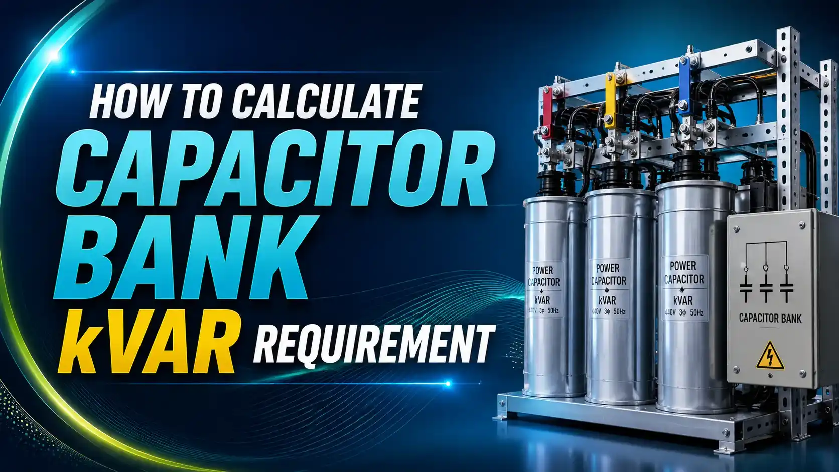
Capacitor bank kVAR requirement is calculated by finding the reactive power difference between a facility's existing power factor and its target power factor at a given real power load, using the formula kVAR = kW × (tan(cos⁻¹PF1) − tan(cos⁻¹PF2)).
Every industrial facility running motors, transformers, and inductive loads pulls two kinds of power from the grid: real power that does actual work, and reactive power that simply sustains magnetic fields without producing output.
Utilities meter both, and once the ratio between them, the power factor, drops below a threshold that's typically around 0.90 to 0.95, most commercial and industrial tariffs apply a penalty. That penalty compounds every billing cycle until it's corrected.
A capacitor bank fixes this by supplying reactive power locally, right at the load, instead of pulling it from the utility. Per Eaton's power factor correction guide for plant engineers, correcting power factor to around 0.95 to 0.98 typically eliminates the penalty entirely while also freeing up transformer and cable capacity.
The sizing math itself is straightforward trigonometry. The complications show up afterward: whether to use fixed or automatic banks, whether harmonics require detuned reactors, and where in the system the bank should physically sit.
This guide walks through the kVAR formula step by step, an interactive calculator you can run with your own numbers, and the real engineering decisions that follow once the sizing is done.
The Power Triangle: Why kVAR Correction Works
Every AC load with inductance draws power along three related axes, and the relationship between them is what makes capacitor sizing possible.
A capacitor bank doesn't touch the kW side of the triangle at all. It supplies a competing reactive current that cancels part of the inductive kVAR, which shortens the vertical leg of the triangle and pulls the kVA hypotenuse down closer to kW. That's the entire mechanism, and it's why power factor correction never changes how much real work a motor does.
The kVAR Sizing Formula, Step by Step
Find the existing power factor angle
Take the current power factor (PF1) from utility bills or a power quality meter, and compute θ1 = cos⁻¹(PF1).
Find the target power factor angle
Choose a target power factor (PF2), usually 0.95 to 0.98, and compute θ2 = cos⁻¹(PF2).
Apply the reactive power difference
kVAR required = kW × (tanθ1 − tanθ2), where kW is the real power load measured at the point of correction.
Round up to a standard bank size
Capacitor banks come in fixed steps (typically 25, 50, or 100 kVAR increments), so the calculated value is rounded up, not down, to avoid under-correcting.
A Real Worked Example
A mid-size manufacturing plant draws 500 kW at an existing power factor of 0.75, which is well into utility penalty territory, and wants to correct to 0.95.
Running the formula: θ1 = cos⁻¹(0.75) = 41.4°, tan(41.4°) = 0.882. θ2 = cos⁻¹(0.95) = 18.2°, tan(18.2°) = 0.329.
kVAR = 500 × (0.882 − 0.329) = 500 × 0.553 = 276.5 kVAR, which rounds up to a standard 300 kVAR bank.
That single correction, per CDE's power factor correction savings guide, typically eliminates the utility's low power factor penalty entirely while also reducing the apparent power (kVA) the facility draws, which frees up transformer and switchgear headroom without any physical upgrade.
Fixed vs Automatic Capacitor Banks
| Type | How It Works | Best Fit |
|---|---|---|
| Fixed bank | A set kVAR value permanently connected to the bus | Loads with stable, predictable reactive demand, like a continuously running motor |
| Automatic bank | Multiple capacitor steps switched in and out by a power factor controller based on real-time load | Facilities with fluctuating load profiles across shifts or production cycles |
| Hybrid (fixed + automatic) | A fixed base bank sized for minimum load, plus automatic steps for peak demand | Large industrial plants wanting to minimize switching cycles on expensive contactors |
Oversizing a fixed bank is a real risk. If reactive load drops below what the bank supplies, the facility swings into a leading power factor, which some utilities penalize just as aggressively as a lagging one. Automatic banks avoid this by only switching in the kVAR the load actually needs at that moment.
Harmonics and Detuned Reactors
Capacitors and harmonics interact in a way that catches a lot of first-time installations off guard.
A capacitor bank installed in a facility with significant variable frequency drive or UPS load without checking for harmonic resonance can amplify existing harmonics instead of just correcting power factor. Detuned filter reactors, tuned to roughly 189 Hz (the 3.78th harmonic) for a 50 Hz system, are the standard fix.
Per Schneider Electric's explainer on detuned reactors, this single design choice is what separates a power factor correction project that works cleanly from one that creates new capacitor failures and nuisance tripping.
Real Capacitor Bank Cost Impact by Size
Cost scales with kVAR, but the payback period usually shortens as the bank gets larger because the avoided monthly penalty grows proportionally.
These are typical automatic low-voltage bank ranges including installation, and vary significantly with voltage class, harmonic filtering requirements, and regional labor cost. Most facilities correcting from a penalized power factor recover this cost within 12 to 24 months purely from avoided utility penalties, according to Eaton's plant engineer guide.
Where to Place the Bank in the System
Individual Load
Capacitor wired directly at a single large motor, correcting only that load and reducing cable current upstream.
Group / Feeder
One bank correcting several smaller loads sharing a distribution panel or feeder.
Central / Bulk
A single large bank at the main switchboard correcting the whole facility's power factor.
Voltage Class
Low-voltage banks for most industrial loads; medium-voltage banks for large motors fed directly at higher distribution voltage.
Switching Transients
Capacitor energizing causes inrush current spikes; contactors must be rated for capacitor switching duty.
Metering Point
Correction should target the utility's actual metering point, not an arbitrary point in the distribution system.
Do's and Don'ts of Capacitor Bank Sizing
✓ Do
- Base kVAR calculations on actual metered kW and power factor, not nameplate ratings
- Target a corrected power factor of 0.95 to 0.98 rather than pushing all the way to 1.0
- Run a harmonic assessment before specifying capacitors on sites with VFDs or UPS loads
- Size automatic banks in steps that match realistic load swing across shifts
✗ Don't
- Oversize a fixed bank, which risks pushing the facility into a penalized leading power factor
- Ignore switching transients when specifying contactors for automatic banks
- Install plain capacitors on a harmonic-rich bus without a detuned reactor
- Correct power factor at a point in the system different from the utility's actual metering location
Reference Materials on Capacitor Bank Sizing
FAQs on Capacitor Bank kVAR Sizing
External References
- Power Factor Correction: A Guide for the Plant Engineer, Eaton
- Savings and Application Guide for Power Factor Correction Capacitors, CDE
- Decoding Detuned Reactors: What and Why, Schneider Electric
What we learn today
- Capacitor bank kVAR requirement is calculated as kW × (tanθ1 − tanθ2), based on the existing and target power factor angles.
- A worked example shows a 500 kW load at 0.75 PF needing about 277 kVAR to reach 0.95 PF, rounding up to a standard 300 kVAR bank.
- Fixed banks suit steady loads while automatic banks step capacitors in and out to match fluctuating reactive demand.
- Sites with VFDs, UPS systems, or other harmonic-generating loads need detuned reactors to avoid resonance with plain capacitor banks.
- Correcting power factor typically eliminates utility penalties and pays back the capacitor bank's cost within 12 to 24 months.