Every non contact level sensor has a short zone under its face where it cannot see the liquid. Learn why it exists, how big it is for radar and ultrasonic units, and how to mount the sensor so your top level stays clear.
This article explains the near zone of radar and ultrasonic level transmitters with real manufacturer values. You also get a mounting height calculator, a solved example and a field troubleshooting table.
What is blocking distance in radar and ultrasonic level transmitters?
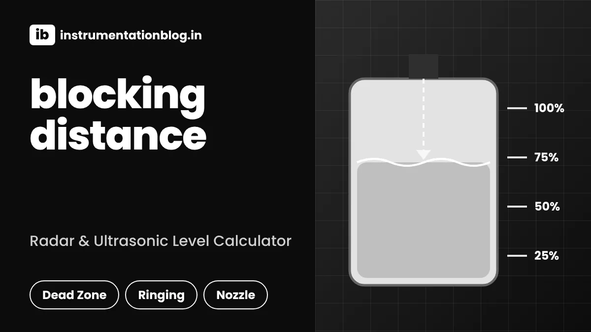
Blocking distance is the short zone directly below the sensor face where a radar or ultrasonic level transmitter cannot measure reliably, because the transducer is still ringing from its own transmit pulse. Endress+Hauser lists 0.25 m for the 1.5 inch Prosonic T FMU30 sensor. Example: if the roof nozzle sits 4.5 m above the tank bottom, the highest level you can read is about 4.25 m.
What Is Blocking Distance?
Blocking distance is the minimum distance between the sensor reference point and the product surface that a radar or ultrasonic level transmitter can measure. Inside this zone the instrument ignores all echoes, so any level that rises into it is either frozen, lost or shown wrongly.
- Other names: dead zone, blanking distance, near zone, near range suppression or minimum measuring distance.
- Cause: the transducer or antenna keeps ringing after the transmit pulse, plus strong nozzle and antenna echoes close to the face.
- Ultrasonic values are usually larger, from about 0.1 m on small sensors to 0.5 m or more on long range sensors.
- Modern 80 GHz radar has a much shorter near zone than older 26 GHz radar.
- Rule: maximum level plus blocking distance plus a safety margin must stay below the sensor face.
If you are new to these sensors, first read how an ultrasonic level transmitter works and how a radar type level transmitter measures distance by time of flight. Both convert the echo time into distance, and the near zone is simply the part of the range where that echo cannot be separated from the sensor itself.
APG Sensors explains that the same ultrasonic transducer both sends and receives the pulse, so it keeps vibrating for a split second after transmitting. The sensor deliberately ignores that short period, and the distance sound travels in that time becomes the blanking distance.
Why Does Blocking Distance Exist?
Blocking distance exists because the sensor must finish transmitting and let its own vibration or antenna ringing die away before it can listen for a weak echo. Any echo that returns during this ringing time is buried under the much stronger transmit signal.
For an ultrasonic sensor the near zone is easy to estimate from the speed of sound and the ringing time. Sound in air travels at roughly 343 m/s at 20 degrees Celsius, and the pulse must go down and come back, so we divide by two.
BD = (c × t_ring) ÷ 2
c = 343 m/s, t_ring = 2 ms
BD = (343 × 0.002) ÷ 2
BD ≈ 0.34 m
Radar works with microwaves, so the ringing is in the antenna and the nozzle rather than in a vibrating membrane. ICS Schneider notes that nozzle reflections, antenna ringing, condensation and deposits all act in this near range, which is why the antenna type and the nozzle geometry matter so much.
Before you change any near zone setting, save the echo curve with the tank at a known low level. Comparing the old and new curve later shows at once whether a fixed nozzle echo or the real surface is being tracked.
What Is the Dead Zone of a Radar Level Transmitter?
The dead zone of a radar level transmitter is usually between a few centimetres and about half a metre, depending on frequency, antenna size and nozzle. Higher frequency radar focuses its beam better and recovers faster, so its near zone is shorter.
| Sensor type | Typical near zone | Source |
|---|---|---|
| Ultrasonic, 1.5 inch FMU30 | 0.25 m | Endress+Hauser manual |
| Ultrasonic, 2 inch FMU30 | 0.35 m | Endress+Hauser manual |
| Short range ultrasonic | About 4 inch | APG Sensors |
| Large ultrasonic | 1.5 ft or more | APG Sensors |
| 26 GHz radar | 0.2 to 0.5 m | Zero Instrument |
| 80 GHz radar | 0.05 to 0.2 m | Zero Instrument |
| Guided wave radar | 0.05 to 0.3 m | Zero Instrument |
Guided wave radar has its own upper transition zone at the top of the probe, so the same mounting logic applies there. Our post on guided wave radar vs non contact radar explains how the probe changes the near zone and when a rod or cable probe is the better choice.
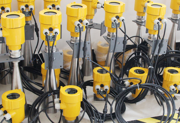
The automation.com article on level technology describes a live ultrasonic test where the sensor showed an error once the water came within about 25 cm of its face. That one demonstration explains most of the high level complaints seen on site.
What Is Blanking Distance in an Ultrasonic Sensor?
Blanking distance in an ultrasonic sensor is the same idea as the near zone, the region in front of the transducer that the sensor ignores while its membrane stops vibrating. APG Sensors states that it depends mainly on transducer frequency and pulse power.
A low frequency, high power transducer reaches further into the tank but rings longer, so its blanking distance is larger. That is why a 15 m range sensor on a silo cannot be used on a shallow sump where the liquid comes close to the roof, as covered in how ultrasonic level measurement works.
- Hides ladder, weld seam and nozzle echoes near the roof
- Stops condensation drops from being read as level
- Gives a stable reading in turbulent fill streams
- Real high levels are ignored and the reading freezes
- Reduces usable span of the tank
- Can defeat overfill alarms if the high high level sits inside it
APG Sensors also notes that many sensors let you program the blanking value, which is handy to skip an obstacle near the top. Treat this as a fine tuning tool and not a cure, because blanking out a real level is far more dangerous than a noisy reading.
How to Calculate Minimum Mounting Height for Blocking Distance
To find the minimum mounting height, add the blocking distance and a safety margin to the maximum level, and compare the result with the roof height. If the sum is higher than the roof, the sensor needs a standpipe nozzle that raises it by the difference.
H_s = H_max + BD + SM
Nozzle raise needed
N = H_s minus H_roof
The Endress+Hauser FMU30 manual says the instrument must be installed so the blocking distance is not undershot even at maximum fill level, and that a pipe nozzle can be used when this cannot be met otherwise. Use the calculator below with your own datasheet value.
H_max = 4.2 m, BD = 0.35 m, SM = 0.10 m
H_s = 4.2 + 0.35 + 0.10
H_s = 4.65 m
Roof = 4.5 m
N = 4.65 minus 4.5
N = 0.15 m standpipe
So the sensor face must sit 0.15 m above the roof flange, or the maximum level must be lowered to 4.05 m. Once the mounting is fixed, the tank volume from level calculator helps you see how much working volume you lose by reducing the top level.
Keep the standpipe smooth inside, wider than the sensor face and free of weld beads. A narrow or rough standpipe creates its own echoes and can make the near zone effectively longer.
Blocking Distance Problems and Symptoms in the Field
When the level enters the blocking distance, the reading usually freezes at a high value, jumps to an empty or error value, or follows a nozzle echo instead of the liquid. These symptoms often appear only during high fill, which makes them easy to miss in testing.
| Symptom | Likely cause | Fix |
|---|---|---|
| Reading stuck near top | Level inside near zone | Lower max level or raise sensor |
| Sudden drop to empty | Echo lost in ringing | Shorter near zone sensor |
| Constant level when empty | Nozzle echo tracked | Echo mapping at low level |
| Noisy high readings | Condensation on face | Heated or 80 GHz sensor |
| Error at high fill only | Blanking set too large | Recheck blanking against span |
Many of these faults look like false echoes, so it helps to read our guide on radar false echo handling alongside this table. A fixed echo stays at the same distance while the true surface moves with filling, which is the quickest way to tell them apart.
For wider fault finding, the level transmitter troubleshooting guide covers wiring, configuration and process causes together. Foam can also weaken the echo near the roof, and why foam affects level sensors explains that effect in detail.
How Does Blocking Distance Affect Overfill Protection?
The highest alarm point must always sit below the blocking distance, otherwise the transmitter is blind exactly when the tank is close to overflowing. Standards such as API 2350 define levels like high high and critical high, and the near zone must stay above all of them.
Read our article on tank overfill protection to API 2350 to see how these levels are set. Zero Instrument also suggests keeping a small safety distance, about 0.1 m, above the highest fill level when the near zone is configured.
- High high alarm level sits below sensor face minus near zone
- Independent high level switch installed where required
- Near zone value matches the actual sensor and nozzle
- Echo curve saved after commissioning
- Proof test includes filling into the top band
How to Reduce Blocking Distance Problems
You reduce near zone problems by choosing a sensor with a shorter zone, raising the sensor on a clean nozzle, or lowering the maximum level. Software settings come last, after the mechanical installation is right.
The right technology depends on the liquid, so check non contact vs guided wave radar selection before ordering. Low dielectric products such as hydrocarbons return a weak echo, which is explained in dielectric constant in level measurement.
In a turbulent or foaming vessel a stilling well can also help, but its inside must be smooth and correctly sized. After any change, verify the reading at the top band as part of radar level transmitter calibration.
Blocking Distance FAQ
Blocking distance is the short zone under the radar antenna where the transmitter cannot read the surface. Typical values run from about 0.05 m on 80 GHz radar to 0.5 m on older 26 GHz radar.
Always confirm the exact figure in the datasheet for your antenna.
In practice both terms describe the same near zone that the sensor ignores after its transmit pulse. Ultrasonic vendors such as APG Sensors prefer blanking distance, while Endress+Hauser manuals use blocking distance.
Some menus call the adjustable setting blanking and the fixed physical limit blocking.
Add the maximum level, the blocking distance and a margin of about 0.1 m to get the sensor face height. With 4.2 m level, 0.35 m zone and 0.10 m margin, the face must be at 4.65 m.
Raise the sensor with a standpipe if the roof is lower.
The reading may freeze at a high value, jump to empty, show an error or follow a nozzle echo. This is dangerous because it usually happens near overflow.
Fix it by lowering the maximum level, raising the sensor or choosing a sensor with a shorter near zone.
An 80 GHz radar usually has the shortest near zone, often a few centimetres, thanks to its narrow beam and fast recovery. Guided wave radar is another good option when foam or low dielectric liquids are present.
Ultrasonic sensors normally need the most clearance.
The most common mistake is setting the near zone to zero or copying a default from another model. A zero value lets ringing and condensation be read as a full tank.
A value that is too large hides real high levels, so match it to the datasheet and nozzle.
Related Articles
- Ultrasonic Level Transmitter Working Principle
- Radar Type Level Transmitter
- Guided Wave Radar Troubleshooting
- Radar Level Antenna Types
- How to Select the Right Level Sensor
External References
- Endress+Hauser Prosonic T FMU30 Operating Instructions (PDF)
- APG Sensors: Ultrasonic Sensors and Blanking Distance
- Wikipedia: Level sensor
What We Learn Today
- Blocking distance is the near zone under a radar or ultrasonic sensor where echoes are ignored because the transducer or antenna is still ringing.
- Ultrasonic sensors have the largest near zone, while 80 GHz radar has the shortest, so the sensor choice decides how close to the roof you can measure.
- Minimum sensor face height equals maximum level plus near zone plus margin, and a smooth standpipe fixes a roof that is too low.