
A level reading that disagrees with the sight glass is one of the most common calls an instrument technician gets. This guide breaks the problem down by technology, with fault tables, two worked calculations and field tips that find the cause quickly.
Each level technology fails in its own typical ways, and the fix depends on knowing which physics you are relying on. Here is a practical, technology by technology method for finding level errors in the field.
What Is Level Transmitter Troubleshooting?
Level transmitter troubleshooting is the step by step process of finding why a level transmitter disagrees with the real level in the vessel, by checking the process conditions, installation, configuration and the measuring principle itself. The first move is always to compare the reading with an independent reference, such as a sight glass, a magnetic level gauge or a manual dip.
- DP level errors usually come from density change, wet leg loss, plugged lines or wrong range.
- Radar errors usually come from false echoes, foam, buildup or wrong tank height settings.
- Guided wave radar errors often sit in the blind zones or come from heavy buildup on the probe.
- Ultrasonic errors come from foam, vapour, dust and temperature changing the speed of sound.
- Check the echo curve or the DP calculation before you recalibrate anything.
The table below is the core of level transmitter troubleshooting, organised by technology. If you are not sure which principle you have, our guide to types of level transmitters gives a quick overview.
Level Transmitter Troubleshooting Fault Table
| Symptom | Technology | Likely Cause | Check |
|---|---|---|---|
| Reads high, slowly rising | DP closed tank | Condensate filling dry leg | Drain the low side leg |
| Reads high or full scale | DP with wet leg | Wet leg partly or fully drained | Refill and check for leaks |
| Reads low with full tank | DP | Density lower than configured | Lab density, recalculate |
| Jumps to a fixed level | Radar, ultrasonic | False echo from internals | Echo curve, mapping |
| Lost echo, fault alarm | Radar, ultrasonic | Heavy foam, turbulence | Echo strength, foam |
| Wrong near top or bottom | GWR | Blind zone, probe end | Range points vs blind zones |
| Drifts over weeks | GWR, radar | Buildup on probe or antenna | Signal quality, clean |
| Shows full when empty | Radar | Multiple reflections | Mounting and orientation |
TIPL, the Indian instrumentation company, explains that a false or unstable radar reading often means the transmitter is not consistently picking the correct reflection. That is why the echo curve, not the 4 to 20 mA value, is the first thing to look at on any radar level transmitter.
TIPL reports an Endress+Hauser case where a radar mounted on a U seal saw multiple reflections and showed full while the pipe was empty. Simply changing the orientation of the radar fixed the reading.
DP Level Transmitter Troubleshooting
A DP level transmitter does not measure level directly, it measures hydrostatic head and divides by the configured density. Any change in density, leg fill or reference pressure therefore shows up as a level error, even if the transmitter itself is perfect.
(for water at SG 1, 1 m ≈ 9.81 kPa)
Indicated level = ΔP ÷ (SGset × 9.81)
True level = Indicated × SGset ÷ SGactual
Range errors are common after a vessel change or a transmitter swap. Recalculate the range from scratch using our guide on calculating DP level transmitter range.
Level Transmitter Troubleshooting for Density and Wet Leg Errors
If the liquid gets lighter, the same level gives less DP and the transmitter reads low. This happens with temperature swings, product changes and dilution, as covered in DP level measurement with varying density.
Actual SG = 0.90, transmitter shows 3.000 m
True level = 3.000 × 1.00 ÷ 0.90
True level = 3.333 m
Error = 0.333 m low = 6.67 % of range
A drained wet leg causes the opposite effect. The low side pressure falls, the DP rises and the transmitter swings high, often straight to full scale.
Design low side head = 6 × 9.81 = 58.9 kPa
Wet leg fully drained: DP rises by 58.9 kPa
Result: output goes high or to overrange
On a closed tank with a wet leg, mark the full leg level on the pipe with paint. Any drop in the leg during rounds tells you about a leak long before the DCS shows a strange level.
Radar Level Transmitter Troubleshooting: False Echoes
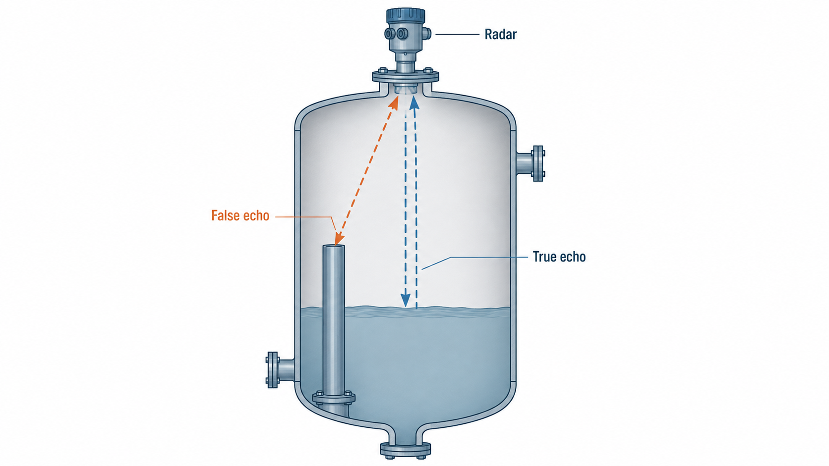
TIPL lists vessel internals, pipes, agitators and nozzles as common sources of unwanted reflections. Modern radars handle these with false echo mapping, which Siemens calls Auto False Echo Suppression and VEGA calls false signal suppression, as explained in radar false echo handling.
Never run a false echo mapping with the tank full, because the device may learn the real surface as a false echo. Map only the region above the current level, and repeat the mapping when internals change.
Foam can absorb most of the radar energy, and turbulence scatters the surface echo. Our article on why foam affects level sensors explains the physics, and agitated vessels need special care with antenna position and damping.
Guided Wave Radar Level Transmitter Troubleshooting
A guided wave radar follows a probe, so false echoes from internals are rarer, but blind zones and buildup become the main issues. The Emerson Rosemount 5300 data sheet states that accuracy in the upper and lower blind zones is worse than plus or minus 30 mm and measurement may not be possible there.
| GWR Item (Rosemount 5300) | Data Sheet Value |
|---|---|
| Accuracy in blind zones | Worse than ±30 mm |
| Lower blind zone with metal centering disc | 20 cm |
| Minimum dielectric, standard coaxial probe | 1.2 |
| Minimum dielectric, rigid single lead | 1.4 |
| Viscosity limit, single lead probe | Up to 8000 cP, buildup allowed |
| Viscosity limit, coaxial probe | Up to 500 cP, buildup not recommended |
| Thinnest interface upper layer | 2.5 cm |
The same data sheet says the 4 and 20 mA points should be set outside the blind zones, and that nozzle height must be added to the upper blind zone for single lead probes. It also says single lead probes are preferred where contamination is a risk.
Some guided wave radars can measure an interface between two liquids with an upper layer as thin as 2.5 cm. The Rosemount 5300 data sheet notes this works only with a fully submerged probe.
Ultrasonic Level Transmitter Troubleshooting
An ultrasonic level transmitter times a sound pulse in the vapour space, so anything that changes or absorbs sound shows up as an error. Foam, heavy vapour, dust, condensation on the face and temperature gradients are the usual causes.
Level enters the blocking distance near the sensor face.
Echo lost or weak.
Speed of sound changes with temperature.
Droplets on the face weaken the signal.
Speed of sound in air rises with temperature, so an uncompensated reading drifts as the vapour space heats or cools. Most sensors measure the temperature at the face, which may not match the whole vapour column in a tall hot tank.
Level Error Calculator for Density Change
Use this calculator during level transmitter troubleshooting whenever the product changes or the temperature moves far from design. If the error is significant, update the configured density or switch to a technology that does not depend on density, using our radar selection guide.
Level Transmitter Troubleshooting Myths
Level Transmitter Troubleshooting Checklist
- Reference level taken at the same time as the reading.
- Correct technology confirmed for foam, vapour, dielectric and buildup.
- Tank height, range and blind zones checked in configuration.
- Echo curve or signal quality reviewed for radar and GWR.
- DP legs and manifold checked, density compared with lab value.
- HART PV, loop current and DCS value compared.
- As found and as left settings recorded.
For a structured calibration after the fault is fixed, follow the 5 point level transmitter calibration method. If the alarm current appears, read it against the NAMUR NE 43 levels before you assume a process overfill.
Save the echo curve of every radar and GWR at commissioning with a known level. Comparing a fault curve with that healthy baseline is the fastest way to spot new false echoes or buildup during level transmitter troubleshooting.
- Echo curves show what the radar really sees.
- Signal quality metrics warn of buildup early.
- HART PV comparison isolates scaling faults.
- Less tank entry and fewer unnecessary removals.
- Needs software or a communicator and training.
- Echo curves vary between makes.
- Cannot fix a wrong technology choice.
- DP errors still need a manual density check.
Rosemount 5300 Guided Wave Radar Data Sheet PDF
Video on False Signal Suppression
Level Transmitter Troubleshooting FAQ
The usual causes are a density different from the configured value, a drained or contaminated leg on DP units, or false echoes on radar and ultrasonic units. Wrong range or tank height settings are also very common.
The first rule of level transmitter troubleshooting is to compare the reading with a manual dip. Then check the echo curve or DP calculation before changing the calibration.
Start with the echo curve to see whether the device is tracking the real surface or a fixed obstruction. Check tank height, range and mounting position against the drawings.
Then look for foam, turbulence, buildup on the antenna and condensation. Run false echo mapping only with a low level and confirm the echo moves with the level.
A drained wet leg or condensate in a dry leg changes the low side pressure and pushes the reading up. A plugged low side line or a higher density than configured has the same effect.
Check the leg fill, blow down the lines and compare the configured density with the actual product. Recalculate the range if the vessel or product has changed.
A false echo is a reflection from something other than the liquid surface, such as a pipe, agitator, ladder or nozzle edge. If it is stronger than the real echo, the transmitter may lock onto it.
Modern radars store these fixed reflections in a mapping and ignore them. Better mounting or a narrower beam also reduces them.
DP and hydrostatic transmitters convert pressure to level using a configured density. If the actual liquid is lighter, the transmitter reads low, and if it is heavier, it reads high.
Radar, guided wave radar and ultrasonic units measure distance, so density has little direct effect. Very low dielectric liquids still need the correct radar probe or antenna.
The top of the probe has a blind zone where accuracy falls or measurement may stop. A nozzle above the tank adds its height to that zone for single lead probes.
Set the 20 mA point below the upper blind zone and check the nozzle dimensions. Buildup near the process connection can also create a false echo there.
Yes, foam can absorb or scatter radar and ultrasonic signals so the echo becomes weak or is lost. Some radars then measure the top of the foam while others see the liquid below it.
DP transmitters ignore light foam because it adds little weight. Guided wave radar usually handles moderate foam better than non contact devices.
Related Articles
- Radar Level Transmitter False Echo Handling
- DP Level Measurement with Varying Density
- Guided Wave Radar Level Transmitter
- Why Foam Affects Level Sensors
- Level Transmitter 5 Point Calibration
External References
- Rosemount 5300 Guided Wave Radar Product Data Sheet, Emerson
- Why Does a Radar Level Transmitter Give False or Unstable Readings, TIPL
- Level Sensor, Wikipedia
What We Learn Today
- Level transmitter troubleshooting starts with an independent reference reading, then checks the physics of the technology used before anyone touches the calibration.
- DP level errors mostly come from density change, wet leg loss, dry leg condensate and wrong range, which a simple hydrostatic calculation reveals.
- Radar and guided wave radar faults show up on the echo curve as false echoes, foam losses, blind zone effects or buildup on the probe.
