
On a ring main or two parallel feeders, fault current can reach a breaker from either side, and a plain overcurrent element cannot tell which side is faulty. Adding direction sensing lets only the breakers nearest the fault trip, so healthy feeders stay in service.
A plain overcurrent relay measures only how much current flows, not which way it flows. The directional overcurrent relay adds a phase angle check against a polarising quantity, which keeps ring mains, parallel feeders and generator incomers selective.
What Is a Directional Overcurrent Relay?
A directional overcurrent relay is a protection device, ANSI number 67, that trips only when current exceeds its pickup setting and also flows in a chosen direction. It combines a normal overcurrent element from the family of protective relays with a direction element that compares the phase angle of the current with a reference called the polarising quantity.
In a simple radial feeder, current always flows from the source towards the load, so ordinary 50 and 51 elements are enough. In a ring main or with parallel feeders, explained in radial and ring power distribution, fault current can arrive from both ends and a non directional relay may trip a healthy section.
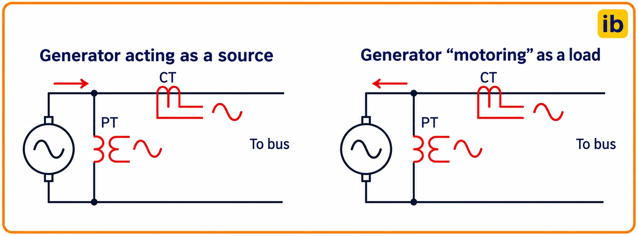
Control.com explains that in an AC system a reverse current is shifted by 180 degrees from the forward current, so direction can be judged only by comparing the current waveform with a reference waveform. That reference is usually a voltage taken from a voltage transformer.
ANSI 67 and 67N Elements Explained
In a directional overcurrent relay, the phase element, ANSI 67, uses phase currents and is meant for phase to phase and three phase faults. The earth element, ANSI 67N, uses residual or zero sequence current and detects earth faults in the selected direction.
Compares each phase current with a quadrature line voltage.
Compares residual current with zero sequence voltage or a neutral current.
Uses negative sequence voltage and current for unbalanced faults.
Control.com notes that negative sequence quantities appear only during asymmetrical faults, which are far more common than balanced three phase faults. Modern numerical relays therefore offer a negative sequence direction element as well as the zero sequence one.
The direction element inside a directional overcurrent relay never trips a breaker on its own. It only gives permission, and the overcurrent element with its pickup and time delay still decides when the trip happens.
Polarising Quantity: The Reference for Direction
Control.com lists three choices of polarising quantity: a line voltage, another current in the system, or a combination where one backs up the other. The relay needs this reference because a current on its own has no direction, only a phase angle relative to something else.
The difficulty is that voltage can collapse during a close in fault, exactly when the relay must work. Numerical relays solve this with voltage memory, holding the prefault voltage phasor for a few cycles, and by using the healthy phase voltages in a quadrature connection.
| Element | Operating Quantity | Polarising Quantity | Typical MTA |
|---|---|---|---|
| 67 phase A | IA | VBC quadrature voltage | 30 to 45 degrees |
| 67 phase B | IB | VCA quadrature voltage | 30 to 45 degrees |
| 67 phase C | IC | VAB quadrature voltage | 30 to 45 degrees |
| 67N voltage polarised | 3I0 residual | 3V0 from open delta VT | Usually 90 degrees leading |
| 67N current polarised | 3I0 residual | Transformer neutral CT current | 0 degrees |
For earth faults, John Horak of Basler Electric describes five combinations of zero sequence voltage and current sources, from fully calculated values to a broken delta VT input and a neutral CT input. The neutral CT is usually a separate current transformer in the star point of a transformer or generator.
Before energising, confirm the VT star point is earthed and the open delta winding is wired to the correct relay terminals. A reversed open delta gives a 67N element that trips for reverse faults and sleeps for forward ones.
Maximum Torque Angle and the Operating Zone
In a directional overcurrent relay, the maximum torque angle, MTA, also called the relay characteristic angle, is the angle at which the direction element is most sensitive. Basler Electric states that the MTA is typically between 30 and 90 degrees, skewed to favour lagging fault current.
For quadrature voltage phase elements, Horak suggests an MTA of about 30 to 75 degrees as a compromise between source and line impedance angles. For zero sequence elements, the MTA is usually 90 degrees leading, and may be moved towards 30 degrees when fault resistance is a concern.
Forward fault if factor is positive, reverse if negative
IDMT time t = TMS × 0.14 ÷ (PSM^0.02 minus 1)
Example, forward phase fault:
φ = 60 degrees, MTA = 45 degrees
cos(60 minus 45) = cos 15 = 0.966, so the fault is forward
Fault current 5 A secondary, pickup 1 A, PSM = 5
t = 0.1 × 0.14 ÷ (5^0.02 minus 1) = 0.43 s
Here φ is the angle by which the operating current lags its polarising voltage as the relay sees it. The forward zone spans 90 degrees on either side of the MTA line, so any current inside that half plane gives a positive factor.
The time part uses the IEC standard inverse curve, covered in detail in IDMT relay characteristics, TMS and PSM. The direction element simply blocks or permits that timer.
Directional Overcurrent Relay Calculator
Second Worked Example: A Reverse Fault
Now let the fault sit behind the directional overcurrent relay, so the current reverses and its angle becomes 60 plus 180, or 240 degrees. The direction factor is cos(240 minus 45) = cos 195 = minus 0.966, so the element restrains even though the current magnitude is the same 5 A.
Type 240 into the calculator to see the reverse result. This is exactly why the incomer relays on two parallel transformers must be directional, otherwise both would trip for a fault on one transformer, as discussed in transformer differential protection.
Where Direction Sensing Is Needed
In Indian process plants, a captive generator running in parallel with the grid is a common case, and the synchronising steps are explained in generator synchronizing procedure. Control.com points out that reverse current makes a generator behave as a load, which the 67 element can detect.
- Keeps rings and parallel feeders selective.
- Allows faster settings on looped networks.
- 67N gives sensitive earth fault direction.
- Numerical relays add memory and sequence elements.
- Needs a reliable VT supply and fuse monitoring.
- Wrong CT or VT polarity reverses the decision.
- Close in three phase faults need voltage memory.
- Grading rings takes more study than radial feeders.
6 Proven Steps to Set a Directional Overcurrent Relay
Fault levels come from the method in short circuit fault current calculation, and the per unit approach in per unit system keeps the arithmetic simple when several voltage levels are involved.
Coordinating Rings and Parallel Feeders
In a ring fed from one source, the relays are graded twice, once for the clockwise direction and once for the anticlockwise direction. Relays at the source end on both legs can be non directional, because current there always flows away from the source.
The grading margin and curve plotting follow the same rules as in circuit breaker coordination and selectivity. For two parallel feeders, the receiving end relays are directional and set to look back into their own feeder, with a short time delay.
Electromechanical directional relays were induction cup units, where the voltage and current coils produced a torque proportional to V × I × cos(φ minus MTA). Numerical relays still describe their direction element with the same torque equation.
Commissioning and Testing a 67 Element
- Verify CT star point direction and VT phasing against drawings.
- Confirm the VT MCB or fuse failure supervision blocks or alarms correctly.
- Read load phasors on the relay display and compare with expected power flow.
- Inject a forward fault vector and confirm trip at the set time.
- Inject a reverse fault vector and confirm the element restrains.
- Sweep the angle to find both zone boundaries around the MTA.
- Record as left settings and the final event log.
A load check with the feeder in service is the most valuable test of any directional overcurrent relay, because it confirms polarity with real primary current. Never open a CT secondary while doing it, for the reasons in CT secondary open circuit risks.
When the feeder exports active power to the bus, the measured load angle should sit near the reverse side of the characteristic. If it does not, stop and recheck CT polarity before you trust the relay.
Common Mistakes With Directional Overcurrent Relay Settings
On resistance earthed systems, earth fault current is limited, so 67N pickup must sit well below the resistor current. Where IEC 61850 is used, direction decisions can also be shared over GOOSE for blocking schemes, as explained in IEC 61850 substation automation.
Troubleshooting Wrong Direction Trips
The most common fault after a retrofit is a directional overcurrent relay that trips for an external fault, which almost always traces back to reversed CT polarity or swapped VT phases. Compare the relay phasor display with a portable phase angle meter reading at the same moment.
A blown VT fuse can also leave the element without a reference, so check that fuse failure logic blocks the 67 trip or switches it to non directional backup. Motor feeders rarely need direction sensing, as shown in motor protection relay types, except where large motors feed fault current back.
Basler Technical Paper on 67 Relaying
Video Lesson on 67 Protection
Directional Overcurrent Relay FAQ
It is a protection relay, ANSI 67, that trips only when current is above pickup and flows in a set direction. It compares the current phase angle with a polarising voltage or current.
This makes it suitable for ring mains and parallel feeders. A plain overcurrent relay there could trip a healthy section and cause a wider outage than needed.
The 67 element uses phase currents and protects against phase faults in the selected direction. It is usually polarised by the quadrature line voltage of the other two phases.
The earth fault element uses residual current and zero sequence voltage or a neutral current. It is the right choice on resistance earthed and solidly earthed networks.
It is the angle at which the direction element has its highest sensitivity. Basler Electric gives a typical range of 30 to 90 degrees, favouring lagging fault current.
The operating zone extends 90 degrees on each side of this line. Currents inside the zone are taken as forward, while currents outside it are taken as reverse.
A current alone has no direction, only a phase angle relative to some reference. The polarising quantity provides that stable reference so the relay can reliably tell forward faults from reverse faults.
Voltage polarising is most common, using a quadrature voltage for phase elements. Current polarising from a transformer neutral is often used for earth fault elements.
All three voltages may fall nearly to zero, so the relay loses its normal reference. Electromechanical relays could fail to operate in this situation.
Numerical relays store the prefault voltage in memory for a few cycles and use it for the decision. Some relays also add a non directional high set element for such faults.
No, the relays at the source end of each leg of the ring can safely be non directional. Current at those points always flows away from the source bus.
The remaining relays are graded in two directions, clockwise and anticlockwise. Each direction is treated like a radial feeder with a margin of about 0.3 seconds.
Inject a forward fault vector with a secondary test set and confirm a trip at the expected time. Then inject a reverse vector of the same size and confirm that the element restrains.
Sweep the current angle to find both zone boundaries around the set angle. Finally, check load phasors in service to prove the CT and VT polarity.
Related Articles
- IDMT Relay Characteristics, TMS and PSM
- Protective Relays Explained
- Circuit Breaker Coordination and Selectivity
- Radial and Ring Power Distribution Systems
- Transformer Differential Protection 87T
External References
- Directional Overcurrent Relaying (67) Concepts, Basler Electric
- Directional Overcurrent (67) Protection, Control.com
- Protective Relay, Wikipedia
What We Learn Today
- A directional overcurrent relay trips only when current is above pickup and flows in the set direction, judged against a polarising voltage or current.
- Basler Electric gives a typical maximum torque angle of 30 to 90 degrees, while quadrature phase elements commonly use about 30 to 45 degrees in practice.
- Ring mains are graded twice, clockwise and anticlockwise, with source end relays left non directional and about 0.3 s between breakers.