
Some loads need more than the right voltage, they need a supply with no direct copper path back to the mains. A transformer with separate windings and a grounded shield gives that clean, local supply and blocks much of the noise riding on the line.
Two windings with no electrical connection between them can do far more than change voltage. An isolation transformer breaks ground loops, reduces shock risk and keeps electrical noise away from sensitive equipment.

What Is an Isolation Transformer?
An isolation transformer is a transformer whose primary and secondary windings are electrically separate, so power passes only through the magnetic field in the core. Most units have a 1:1 ratio, although any transformer with separate windings provides the same galvanic isolation.
Because there is no conductive path between input and output, a fault or disturbance on the supply side cannot flow straight through to the load. The secondary becomes a new, local source whose relationship to earth the designer decides.
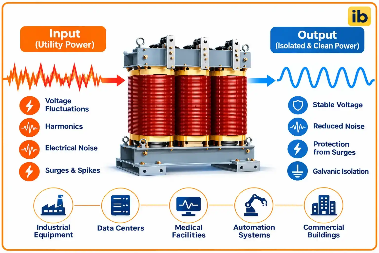
Rex Power Magnetics points out that even a 600 V to 208Y/120 V distribution transformer gives voltage conversion and galvanic isolation at the same time. So the term describes a function, while the 1:1 shielded unit is simply its most common form.
How Galvanic Isolation Works
The secondary voltage follows the turns ratio exactly as in any power transformer, explained in transformer turns ratio. Only the 50 Hz magnetic coupling carries energy, while direct current, ground potential differences and most common mode disturbances have no path across.
This is the same principle used at signal level by an optocoupler, except that the isolation transformer handles kilowatts of power instead of milliamps of signal.
In a standard isolation transformer, the windings still couple through a small stray capacitance. That capacitance, not the magnetic path, is what lets fast spikes jump from primary to secondary.
The Electrostatic Shield and Noise Attenuation
To block that capacitive path, manufacturers place a thin copper or aluminium foil, the electrostatic shield, between the windings and connect it to earth. Rex Power Magnetics notes that the shield reduces capacitive coupling, while its real benefit depends on construction, grounding and the installation impedance.
Hammond Power Solutions publishes typical figures for its shielded units. A standard single shield gives about 60 dB of common mode noise attenuation and 10 dB of transverse mode attenuation over 100 Hz to 1 MHz, while a single shield with under 30 pF coupling reaches 100 dB and 40 dB.
Double shields give 60 to 80 dB and triple shields 65 to 80 dB of common mode attenuation, so Hammond notes that the third shield adds little. Transverse mode noise, which appears between line and neutral, needs filters as well, as covered in electromagnetic interference.
Bond the shield terminal to the transformer earth with the shortest possible strap. A long, thin shield lead adds inductance and wipes out most of the high frequency attenuation you paid for.
Types of Isolation Transformer
1:1 unit with one electrostatic shield for clean supply to electronics.
Low secondary voltage, built to IEC 61558 2 6 for SELV circuits.
Built to IEC 61558 2 15 to feed IT systems in operating theatres.
Designed for non sinusoidal current of rectifier loads.
Extra thermal margin for harmonic heating.
Rex Power Magnetics stresses that drive loads need a drive isolation transformer built for that duty, not a general purpose unit. Rectifier input currents are rich in harmonics, as shown in power harmonics explained, and they overheat ordinary windings.
K Factor Rating Formula
Harmonic currents raise eddy current losses in the windings roughly with the square of harmonic order, so a transformer feeding computers, UPS systems or drives can overheat below its nameplate kVA. The K factor expresses that extra heating, using the harmonic spectrum measured as described in THD calculation for power systems.
Irms² = I1² + I3² + I5² + I7² + ...
Example with I1 = 100, I3 = 20, I5 = 15, I7 = 10 percent
Sum of squares = 1 + 0.04 + 0.0225 + 0.01 = 1.0725
Weighted sum = 1 + 0.36 + 0.5625 + 0.49 = 2.4125
K = 2.4125 ÷ 1.0725 = 2.25, so select a K 4 rated unit
Standard ratings are K 4, K 9, K 13, K 20 and higher, and you always round up to the next rating. Rex Power Magnetics notes that a K factor transformer withstands harmonic heating, while a harmonic mitigating transformer actually reduces certain harmonic effects.
Isolation Transformer K Factor Calculator
Second Worked Example: Sizing the kVA
A control panel draws 4 kW at a power factor of 0.8, which is 4 ÷ 0.8 = 5 kVA. Adding 25 percent for future loads gives 6.25 kVA, so the next standard size of 7.5 kVA is chosen, using the method in transformer kVA rating calculation.
At 230 V the secondary full load current is 7500 ÷ 230 = 32.6 A, which sets the outgoing breaker and cable. Allow also for magnetising transformer inrush current, which can trip a small primary breaker on switch on.
Isolation Transformer vs Autotransformer
| Feature | Isolation Transformer | Autotransformer |
|---|---|---|
| Windings | Two separate windings | One tapped winding |
| Galvanic isolation | Yes | No |
| Size and cost for same kVA | Larger, higher cost | Smaller, cheaper |
| Noise blocking | Good with shield | Very little |
| Shock protection | Can create a floating or new earthed supply | None, output tied to input |
| Typical use | Panels, medical, test benches | Motor starting, voltage boost |
An autotransformer is efficient for small voltage changes, but its output is metallically connected to the input. When isolation is the reason for buying the unit, only a double wound design will do the job.
Medical IT Systems and Safety Isolation
Operating theatres and intensive care units use the IT system, where the isolation transformer secondary is not earthed and an insulation monitoring device raises an alarm on the first fault. Rex Power Magnetics notes that IEC 61558 2 15 covers isolating transformers for medical IT systems, and the IT earthing concept is explained in TN, TT and IT earthing systems.
IEC 60364 7 710 limits these medical units to a rated output between 0.5 kVA and 10 kVA, and the monitor alarms when insulation falls to 50 kΩ. A first earth fault therefore gives a warning instead of a trip, so life support equipment keeps running.
In a medical IT system the letters IT describe the relationship to earth, isolated and terra, not information technology. The same letters appear in IEC earthing system names such as TN and TT.
Grounding the Secondary Correctly
In industrial panels the secondary neutral is normally bonded to earth at the transformer, which makes it a separately derived system with its own reference and fault path. A floating secondary can drift to high voltage by capacitance, as explained in floating vs grounded voltage.
An isolation transformer also breaks ground loops between two buildings with different earth potentials. This is useful for analyser shelters and remote panels that share signal cables with the main control room.
Never bond the secondary neutral at both the transformer and a downstream board. Two bonds let neutral current flow on the earth conductor, which brings back the very noise the transformer was meant to remove.
Selection Checklist
- Confirm primary voltage, secondary voltage and phase count.
- Size kVA from real load plus 20 to 25 percent margin.
- Choose single, double or low capacitance shielding for the noise level.
- Check harmonic content and select a K rating if needed.
- Specify insulation class and temperature rise.
- Decide whether the secondary is earthed or monitored as IT.
- Ask for routine test reports including insulation resistance.
Factory tests should include the checks listed in transformer routine and type tests. On site, an insulation resistance test between windings and from each winding to the shield confirms that isolation is intact.
Advantages and Limitations
- Galvanic isolation from the supply.
- Blocks common mode noise with a shield.
- Breaks ground loops between buildings.
- Creates a new earthed or IT supply.
- Reduces shock risk on test benches.
- Larger and costlier than an autotransformer.
- Adds losses and some voltage drop.
- Little effect on transverse mode noise without filters.
- Inrush current on switch on.
- Needs correct earthing to work.
6 Smart Uses of an Isolation Transformer
In plants where drives and PLCs share one supply, a shielded transformer on the control circuits helps with the power quality issues in VFD and PLC systems. It also complements a UPS, which handles outages but not always noise.
Isolation Transformer Noise Attenuation PDF
Watch How It Works
Isolation Transformer FAQ
It transfers power from primary to secondary only through the magnetic core, with no wire connection between them. The load therefore gets a supply that is galvanically separated from the mains.
This separation breaks ground loops and lets the designer set a new earth reference. With an electrostatic shield it also blocks a large share of common mode noise.
Touching one secondary conductor of a floating supply gives little current because there is no return path through earth. That is why service benches and medical systems often use isolated supplies.
Touching both secondary conductors together still gives a full shock. Isolation removes the earth path but never removes the voltage between the two output wires.
It is an earthed metal foil placed between the primary and secondary windings. It intercepts the stray winding capacitance that would otherwise carry fast spikes and switching noise across.
Hammond quotes about 60 dB of common mode attenuation for a standard single shield. The shield only works well when its earth strap is short and solid.
An autotransformer uses one tapped winding, so its output is directly connected to its input. It is smaller, lighter and cheaper but gives no galvanic isolation at all.
An isolation transformer has two separate windings and costs more for the same rating. Choose it whenever separating the load from the supply is the real goal.
It shows how much harmonic heating a transformer can handle beyond a pure sine wave load. Higher values such as 13 or 20 suit loads with many electronic power supplies.
You calculate K from the measured harmonic currents and then round up to the next standard rating. Our calculator gives about 2.25 for a typical mixed load, which needs a K 4 unit.
In most industrial panels the neutral is bonded to earth at the transformer to form a separately derived system. This gives a defined fault path so breakers can trip quickly.
Hospitals instead use an unearthed IT secondary with an insulation monitor. There a first fault only raises an alarm, so critical equipment keeps running safely.
Measure insulation resistance between primary and secondary and from each winding to the shield and core. Then check the no load secondary voltage against the nameplate ratio.
Confirm that the shield and neutral bonds are tight and short. Finally run the load and check temperature rise with a thermal camera after an hour or two.
Related Articles
- What Is Galvanic Isolation
- Transformer Turns Ratio and Secondary Voltage
- Power Harmonics Explained
- Ground Loop Causes and Prevention
- How to Calculate Transformer kVA Rating
External References
- Typical Shielded Noise Attenuation, Hammond Power Solutions
- Isolation Transformer Purpose, Functions and Uses, Rex Power Magnetics
- Isolation Transformer, Wikipedia
What We Learn Today
- An isolation transformer passes power only through its magnetic core, so the load gets a supply with no direct copper path back to the mains.
- An earthed electrostatic shield between windings gives roughly 60 dB of common mode noise attenuation in a standard single shield design, according to Hammond.
- K factor is the sum of squared harmonic currents times their order squared, and a typical mixed load with K of 2.25 needs a K 4 unit.