
A turbulent, foaming or low dielectric liquid surface can scatter radar signals until the level reading jumps or vanishes completely. A properly designed pipe around the beam calms the surface, guides the microwaves and turns a difficult tank into an easy one.
A stilling well is a vertical pipe that isolates a calm liquid surface from turbulence, foam and agitation inside a tank. Its diameter, slots and finish decide whether a radar or guided wave radar reading stays stable and accurate.
What Is a Stilling Well?
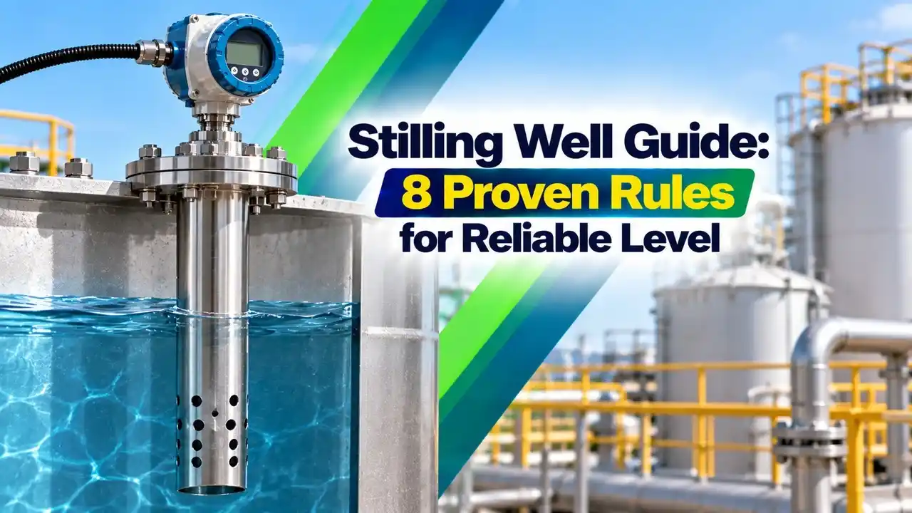
A stilling well is a vertical pipe installed inside a tank, sump or channel, open to the liquid through holes or slots, so that the surface inside the pipe stays calm while the main liquid moves. Any level sensor that looks down the pipe, such as a radar level transmitter, then sees a steady, flat target.
The idea is old and simple, borrowed from river gauging, where a float inside a pipe ignores waves while still following the true water level. In process plants the same pipe is called a still pipe, sounding pipe or guide pipe, and it is closely related to the external chamber used by a bypass level indicator.
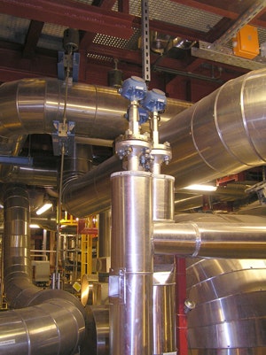
Chemical Processing explains, in an article by Emerson level specialist Sarah Parker, that external chambers cope with turbulence and allow easier servicing of the device. The same article recommends multiple holes or slots on one side of the pipe so that liquid flows through freely.
A metal pipe acts as a waveguide for microwaves. Inside it, radar energy cannot spread out, so even a weak echo from a low dielectric liquid comes back strong.
Why Radar Needs a Calm Surface
Free space radar relies on a reflection from the liquid surface. Turbulence tilts that surface and scatters the echo, while foam absorbs energy, as explained in why foam affects level sensors.
Liquids with low dielectric constant, such as hydrocarbons, LPG and solvents, reflect only a small part of the signal in the first place. Mixers, inlet jets and internal structures add false echoes that the transmitter must reject, a topic covered in radar level transmitter false echo handling.
The pipe solves all three problems at once, because it blocks agitation, keeps most foam outside and concentrates the radar energy. Plants with mixers should compare it with the options in level measurement in agitated vessels.
Stilling Well vs Bypass Chamber vs Open Tank
| Arrangement | Location | Main Benefit | Main Drawback |
|---|---|---|---|
| Stilling well inside the tank | Hangs from a top nozzle | No extra process connections | Hard to remove for cleaning |
| Bypass chamber outside | Side nozzles top and bottom | Isolation valves allow service in run | Liquid can cool or settle |
| Open tank, no pipe | Direct view of surface | Simple, no buildup in a pipe | Sensitive to foam and turbulence |
A stilling well inside the vessel follows the process temperature, which avoids density differences between the pipe and the tank. A bypass chamber, by contrast, can be isolated and drained while the tank stays in service.
When a bypass chamber carries a hot or viscous liquid, add insulation or heat tracing so the liquid inside matches the tank. A cooler chamber column reads a different level from the vessel.
Types of Stilling Well Arrangements
Vertical slots along the whole pipe let liquid enter at every height.
Rows of round holes drilled along one side.
Pipe open at the bottom with a vent hole near the top.
Pipe outside the vessel joined by two nozzles.
Water utilities and irrigation channels use a bottom open stilling well with a pressure or float sensor, as part of the open channel flow measurement station. Refinery tank farms use slotted full length pipes for radar tank gauging, described in automatic tank gauging explained.
8 Proven Stilling Well Design Rules
Varec, in its radar gauging application guide, adds that the welding seam should be as smooth as possible and on the same axis as the slots. It also warns that a horn antenna in a pipe gives lower accuracy than in free space unless the well is built carefully.
The antenna must match the pipe, so check the options in radar level selection, non contact vs guided wave before ordering. Many suppliers sell a dedicated still pipe antenna that fits the pipe bore exactly.
Slots arranged 180° apart keep the inside of the pipe electrically symmetrical. Slots at 90° disturb the polarisation of the radar wave and create spurious echoes.
Radar Speed Inside a Stilling Well
Inside a metal pipe, microwaves travel at a group velocity lower than in free space, so the radar must know the pipe inner diameter to correct the distance. For the basic TE11 mode in a round pipe, the cutoff frequency depends only on the diameter.
Distance factor: k = 1 ÷ √(1 minus (fc ÷ f)²)
Uncorrected error = (k minus 1) × L
c = 299792458 m/s, D = inner diameter, f = radar frequency, L = distance
Example:
D = 100 mm, f = 26 GHz, L = 5 m
fc = 299792458 ÷ 0.1706 = 1.76 GHz
fc ÷ f = 0.0676, squared = 0.00457
k = 1 ÷ √0.99543 = 1.00229
Error = 0.00229 × 5000 mm = 11.5 mm
The transmitter applies this correction automatically once you enter the pipe diameter in its setup menu. Forgetting the setting is a common reason for a steady offset that grows with distance from the antenna.
Stilling Well Radar Correction Calculator
Second Worked Example: Small Pipe, Low Frequency
Now take a 50 mm pipe with an older 6 GHz radar and the same 5 m distance. The cutoff becomes 3.51 GHz, the ratio fc ÷ f is 0.586 and k rises to 1.234.
Without correction the radar would read about 6.17 m instead of 5 m, an error of nearly 1.17 m. This is why low frequency radars need larger pipes, while 26 GHz and 80 GHz units suit compact pipes much better.
Guided Wave Radar as an Alternative
A guided wave radar level transmitter sends pulses down a rod or cable, and inside a stilling well or chamber the pipe forms a coaxial path around the probe. Chemical Processing notes that GWR in chambers is simpler to install and keeps its accuracy independent of pipe dimensions.
The same article prefers single rod probes, because they resist buildup, and says the probe must hang vertically without touching the chamber wall. The trade offs between the two radar families are compared in guided wave radar vs non contact radar.
- Calms turbulence from mixers and inlets.
- Keeps most surface foam away from the beam.
- Strengthens echoes from low dielectric liquids.
- Blocks false echoes from tank internals.
- Allows radar on floating roof tanks.
- Sticky or crystallising liquids can plug holes.
- Long pipes need supports and careful welding.
- Cleaning needs tank access unless a bypass is used.
- Level lags slightly behind fast level changes.
For a liquid that coats surfaces, prefer a larger pipe and a flushing connection near the top. Schedule flushing with the cleaning of the tank so buildup never closes the slots.
Where Stilling Well Designs Are Used
Floating roof tanks already carry a guide pole for the roof, and that pole is often slotted and reused as the still pipe for custody transfer radar. Where precision is everything, compare radar with the servo level gauge, which also runs inside a pipe.
Installation and Commissioning Checklist
- Pipe is metal, straight, vertical and of constant bore.
- Slot width below D ÷ 10 and rows 180° apart.
- Joints have gaps under 1 mm and smooth inner welds.
- Vent hole above maximum level is open.
- Antenna type matches the pipe diameter.
- Pipe inner diameter entered in the transmitter setup.
- Echo curve checked at empty, mid and high level.
- Supports fitted on long pipes in agitated tanks.
After installation, record the echo curve at several levels and verify the reading with a manual dip, following the approach in level transmitter 5 point calibration. A clean echo curve with one strong peak is the best sign that the pipe works as intended.
Troubleshooting Stilling Well Readings
A reading that stays fixed while the tank level changes usually means the slots or bottom opening are blocked. A reading that jumps between two values often points to a weld bead, a burr or a joint gap that reflects part of the signal.
If the pipe works at low level but fails near the top, check whether the antenna sits too close to the first slot or the vent hole. For new projects, the broader guidance in how to select the right level sensor helps decide whether a pipe is needed at all.
Radar Gauging Applications Guide
Stilling Well With Guided Wave Radar Video
Stilling Well FAQ
It is a vertical metal pipe inside or beside a tank that connects to the liquid through holes or slots. The liquid surface inside the pipe stays calm even when the tank is turbulent.
A radar or float sensor then measures that calm surface. The reading follows the true tank level without the noise caused by waves, mixers and foam.
The metal pipe acts as a waveguide, so microwave energy cannot spread out and get lost. Even a weak reflection from a low dielectric liquid returns to the antenna strongly.
The pipe also hides internal structures such as heating coils and ladders. These would otherwise create strong false echoes that confuse the transmitter during normal operation.
Chemical Processing, quoting Emerson, recommends 75 mm or 100 mm chambers because smaller pipes raise the risk of buildup. The antenna must also match the pipe bore closely.
Varec advises a constant diameter that is not larger than the antenna. Avoid reducers or sudden steps, since each one creates an unwanted echo inside the pipe.
Varec recommends slot widths below one tenth of the pipe diameter so that little radar energy leaks out. In a 100 mm pipe that means every slot must be narrower than 10 mm.
Place slot rows 180° apart rather than 90° apart. Keep the inner surface fully deburred and the weld seam ground smooth and aligned with the slots.
Microwaves travel more slowly inside a pipe than in free space, so the measured distance would read too long. The amount depends on the pipe diameter and the radar frequency.
In a 100 mm pipe at 26 GHz the error is about 11.5 mm at 5 m. In a 50 mm pipe at 6 GHz the same distance could read more than a metre too long.
Yes, guided wave radar works very well inside a stilling well or external chamber. The pipe and probe form a coaxial path, which gives a strong echo even from difficult liquids.
Use a single rod probe kept vertical and away from the wall. Rigid probes suit short chambers, while flexible probes must stay taut in longer ones.
No, heavy foam can still enter through the slots and sit on the surface inside the pipe. The pipe usually reduces foam thickness but does not remove it entirely.
Place the stilling well away from foam sources such as inlet jets. Add a flushing connection if foam or buildup tends to collect inside the pipe.
Related Articles
- Radar Type Level Transmitter
- Guided Wave Radar Level Transmitter
- How Bypass Level Indicators Work
- Why Foam Affects Level Sensors
- Automatic Tank Gauging Explained
External References
- Radar Gauging Applications Guide, Varec
- Make the Most of Radar, Chemical Processing
- Level Sensor, Wikipedia
What We Learn Today
- A stilling well is a slotted metal pipe that calms turbulence and foam so a radar sees a steady surface and a strong echo from low dielectric liquids.
- Good design keeps a constant bore, slots narrower than D ÷ 10, rows 180° apart, joint gaps under 1 mm and smooth, deburred inner welds.
- Radar must know the pipe diameter because microwaves travel slower inside a pipe; at 26 GHz in 100 mm pipe the error is 11.5 mm at 5 m.