
An ADC can only be as accurate as the voltage it compares every input against. Choose the wrong reference chip and a 16 bit converter quietly performs like a 10 bit one, no matter how clean the rest of the board is.
Every ADC, DAC and precision sensor circuit measures against a fixed voltage. Picking the right voltage reference means balancing initial accuracy, temperature drift, noise, current and cost for the job at hand.

What Is a Voltage Reference?
A voltage reference is a circuit or IC that produces a precise, stable DC voltage which stays nearly constant with changes in supply, load, temperature and time. It sets the full scale of every ADC and DAC, so its error appears directly in the measurement.
A power regulator also gives a fixed voltage, but it is designed to deliver amps with modest accuracy. The regulator types in linear vs switching voltage regulators typically hold their output within a percent or two, while a precision reference aims for hundredths of a percent.
Think of the voltage reference as the ruler of the measurement system. If the ruler is 0.5 percent short, every reading is 0.5 percent wrong, even if the ADC itself is perfect.
Series and Shunt Topologies Compared
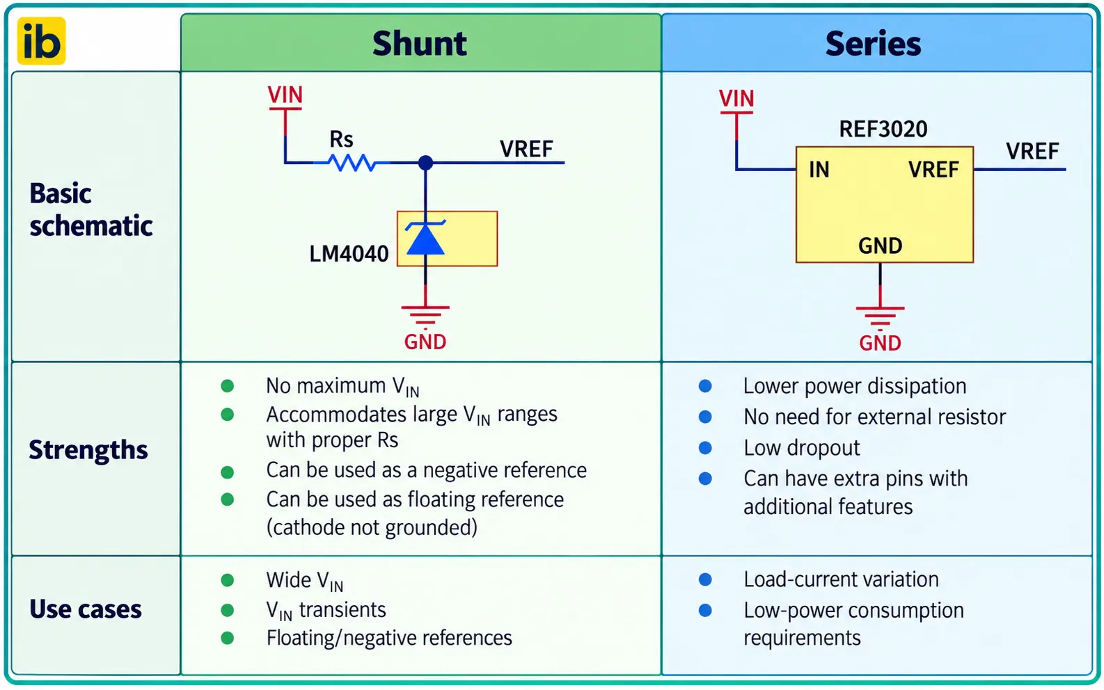
A series voltage reference has three terminals, input, output and ground, and works like a precision linear regulator with a pass transistor in series with the load. A shunt reference has only two terminals and works like a precision zener, sitting in parallel with the load and fed through a resistor.
- Low quiescent current that stays constant.
- Better initial accuracy and tempco on average.
- Efficient when load current varies widely.
- Simple, no external resistor to calculate.
- Works from any supply through a resistor.
- Easy to make negative or floating references.
- Only two pins, very low cost.
- Handles supplies far above 40 V.
Analog Devices advises that if you need better than 0.1 percent initial accuracy and a 25 ppm per °C tempco, you should probably select a series voltage reference. The same article notes that above about 40 V of supply, a shunt reference may be your only choice.
Analog Devices also shows how load variation changes the picture. In its example with load current from 1 µA to 1 mA, the series part dissipated about 32.78 µW on average against 4.895 mW for the shunt design, because the shunt resistor must always be sized for the worst case.
The silicon bandgap voltage is close to 1.2 V, which is why so many bandgap reference chips start from about 1.22 V. Higher outputs such as 2.5 V or 4.096 V are produced by an internal amplifier with precise gain.
Voltage Reference Core Technologies
A reverse biased junction breaks down at a fixed voltage.
Two transistor voltages with opposite drift are added to cancel temperature change.
The breakdown happens below the silicon surface, away from contamination.
JFET pairs or stored charge give low drift and low noise.
A plain zener, covered in what is a Zener diode, drifts with temperature and current and has high noise, so it serves only rough references.
The bandgap circuit adds a base emitter voltage, which falls with temperature, to a scaled difference of two base emitter voltages, which rises with temperature. The transistor behaviour behind it is described in BJT currents and voltages.
TL431: The Popular Adjustable Shunt
The TL431 is a three pin adjustable shunt reference with an internal 2.495 V bandgap, a comparator style error amplifier and an output transistor. Two resistors set the output anywhere from 2.495 V up to 36 V.
Vref of TL431 = 2.495 V
Example: R1 = 10 kΩ, R2 = 10 kΩ
Vout = 2.495 × (1 + 1) = 4.99 V
Keep cathode current at 1 mA or more for full regulation
The TL431 is found in almost every offline power supply, where it drives an optocoupler in the feedback loop. As a precision reference it is only moderate, since its tolerance grades are 0.5, 1 and 2 percent, but it is excellent for comparator thresholds and supervisor circuits.
Most TL431 oscillation complaints come from a capacitor across the cathode of the wrong size. Check the stability boundary chart in the datasheet before adding output capacitance, or leave it out completely.
7 Smart Voltage Reference Specs to Check
Texas Instruments groups initial accuracy into three tiers in its selection note, high below 0.1 percent, medium from 0.1 to 0.5 percent and low above 0.5 percent. A one time calibration in software can remove initial error, but it cannot remove drift and noise.
Temperature coefficient is usually specified by the box method, the total output change divided by the voltage and the temperature span. TI shows that a 100 ppm per °C part can drift about 0.7 percent across 0 to 70 °C, which already exceeds one LSB of an 8 bit converter.
Noise matters most for high resolution converters, because it cannot be calibrated out. TI recommends that the reference noise be at least 5 times smaller than the ADC noise, and the effect on dynamic range is explained in signal to noise ratio.
Many precision voltage reference datasheets quote a thermal hysteresis figure. After a hot and cold cycle, the output may not return to its original value, so the part carries a small permanent offset until it is cycled again.
ADC Error Budget Formula
The voltage reference error adds directly to the gain error of the converter. The concept of error expressed as a fraction of full scale follows the same logic as in instrument accuracy and error.
Error in mV = Vref × ppm ÷ 1000000
1 LSB = Vref ÷ 2 to the power N
Example: 2.5 V reference, 0.1 %, 25 ppm per °C, 25 °C to 70 °C, 12 bit ADC
Initial = 0.1 × 10000 = 1000 ppm
Drift = 25 × 45 = 1125 ppm
Total = 2125 ppm = 2.5 × 2125 ÷ 1000000 = 5.31 mV
1 LSB = 2.5 ÷ 4096 = 0.61 mV
Error = 5.31 ÷ 0.61 = 8.70 LSB
This is a worst case linear sum, which is the safe choice for industrial designs. Some engineers use a root sum square total when the error sources are independent, which gives a smaller but less conservative number.
Voltage Reference Error Calculator
Second Worked Example: Sizing a Shunt Resistor
Embedded Computing Design gives an industrial example with a 2.5 V LM4040 shunt fed from a 12 to 48 V supply and a load of 0.1 to 1 mA. The LM4040 needs at least 60 µA and allows at most 15 mA of current.
R min = (Vin max minus Vref) ÷ (I load min + I shunt max)
R max = (12 minus 2.5) ÷ (1 mA + 0.06 mA) = 8.96 kΩ
R min = (48 minus 2.5) ÷ (0.1 mA + 15 mA) = 3.01 kΩ
Choose a standard resistor between 3.01 kΩ and 8.96 kΩ
Pick a value near the upper end to reduce the wasted voltage reference feed current, but leave margin for resistor tolerance and supply dips. Then check the resistor wattage at the maximum input, since (48 minus 2.5) squared divided by the resistance can reach several hundred milliwatts.
The same article compares battery life in a portable design and finds about 13.9 days with a series reference against 2.5 days with a shunt. That result shows why battery powered loggers almost always use series parts.
Place the shunt feed resistor close to the supply side and keep the reference pin trace short. Long traces pick up noise that the ADC will faithfully convert into wrong codes.
Layout, Bypassing and Buffering Tips
Every voltage reference needs the input and output capacitors listed in its datasheet, because some series parts become unstable with too little or too much capacitance. The general role of these parts is explained in how decoupling capacitors work, and the capacitor ESR can also affect stability.
A SAR converter draws sharp current pulses from its reference pin during every conversion. TI shows a case where the ADC draws up to 600 µA, so many designs add a unity gain buffer and a large ceramic capacitor right at the pin.
Route the reference ground to the ADC ground at a single point on a solid plane, as recommended in ground plane PCB design. Keep the reference away from hot parts, because board temperature gradients cause drift and thermocouple effects.
- Output voltage matches the ADC full scale range.
- Initial accuracy meets the need, or a calibration step is planned.
- Tempco times the real temperature span fits the error budget.
- Noise is at least 5 times below the ADC noise.
- Input and output capacitors match datasheet stability limits.
- Buffer is used when the ADC reference pin draws pulsed current.
- Shunt resistor is checked at minimum and maximum supply.
- Long term drift fits the calibration interval of the product.
Selecting a Reference for Industrial Instruments
In a PLC analog card or transmitter, the voltage reference sets the accuracy of the 4 to 20 mA reading, as discussed in analog signal resolution in PLC. A 16 bit card with a 50 ppm per °C part can lose several counts of accuracy over a hot Indian summer inside a panel.
Zero and span shifts in field instruments often trace back to drift of this part, and the symptoms are described in thermal effect on sensors. For such products, choose a low tempco series voltage reference and verify it in a thermal chamber from 0 to 60 °C.
| Application | Typical Choice | Key Spec |
|---|---|---|
| Hobby MCU board | Internal ADC reference or TL431 | Low cost |
| PLC analog card | Series bandgap, 0.05 % | Tempco below 10 ppm per °C |
| Battery data logger | Low power series reference | Quiescent current in µA |
| Handheld multimeter | Series or buried zener | Low noise, stability |
| Offline SMPS feedback | TL431 shunt | Wide supply range |
Voltage Reference Selection Guide PDF
TL431 Shunt Circuits Video
Voltage Reference FAQ
It is a circuit that produces a precise, stable DC voltage for measurement and conversion. It sets the full scale of ADCs and DACs in instruments and controllers.
Unlike a power regulator, it supplies only small currents with high accuracy. Typical outputs are 1.25 V, 2.5 V, 3 V and 4.096 V for converter use.
A series type has three pins and works like a precision linear regulator in series with the load. A shunt type has two pins and sits across the load with a feed resistor.
Series parts are more efficient with changing loads and usually more accurate. Shunt parts work from any supply voltage and are easy to use for negative rails.
It is the change of output voltage per degree of temperature, expressed in parts per million. A 10 ppm per °C part on 2.5 V drifts 25 µV for every degree.
Datasheets normally use the box method across the full temperature range. Multiply the tempco by the real temperature span to estimate the drift in your product.
The TL431 is an excellent low cost adjustable shunt for supplies, comparators and supervisors. Its tolerance grades of 0.5, 1 and 2 percent are too loose for precision measurement.
For a 12 bit or better ADC, choose a dedicated series part with low tempco. Use the TL431 where wide voltage range and low price matter more than accuracy.
The voltage reference sets the full scale value, so its error becomes a gain error on every reading. A 0.1 percent error gives about 4 LSB of error on a 12 bit converter.
Add drift over temperature and the total can easily reach 8 or 9 counts of error. Always compare the reference error budget with the resolution you actually need.
The breakdown region is formed below the silicon surface instead of at the surface. There it is shielded from surface charge and contamination that cause noise and drift.
This structure offers very good long term stability for meters and calibrators. The trade off is a higher breakdown voltage, so the supply must usually be above about 7 volts.
Most parts need an input capacitor and many need a specific output capacitor for stability. The datasheet gives the allowed range of capacitance and ESR for each part.
Some series designs oscillate with too little capacitance, and some shunt designs oscillate with too much. Follow the stability chart exactly and place the parts close to the pins.
Related Articles
- ADC Working Principle Explained
- What Is a Zener Diode
- Linear vs Switching Voltage Regulators
- Analog to Digital Conversion Explained
- Operational Amplifier Basics
External References
- Voltage Reference Selection and Design Tips for Data Converters, Texas Instruments
- Shunt versus Series: How to Select a Voltage Reference Topology, Embedded Computing Design
- Voltage Reference, Wikipedia
What We Learn Today
- A voltage reference sets the full scale of every ADC and DAC, so its initial accuracy, drift and noise appear directly as measurement error.
- Series types suit changing loads and battery designs, while shunt types such as the TL431 suit high supply voltages, negative rails and low cost.
- Add initial accuracy and tempco times temperature span to get total ppm error, then compare it with one LSB of your converter.