
When grid power fails at night, nobody should have to run to the generator room and start the DG by hand. An automatic mains failure panel senses the outage, starts the engine, shifts the load and hands it back safely when the grid returns.
An AMF panel watches the utility supply and starts a standby diesel generator the moment the mains fail. It then transfers the load, protects the engine and returns everything to normal without human action.
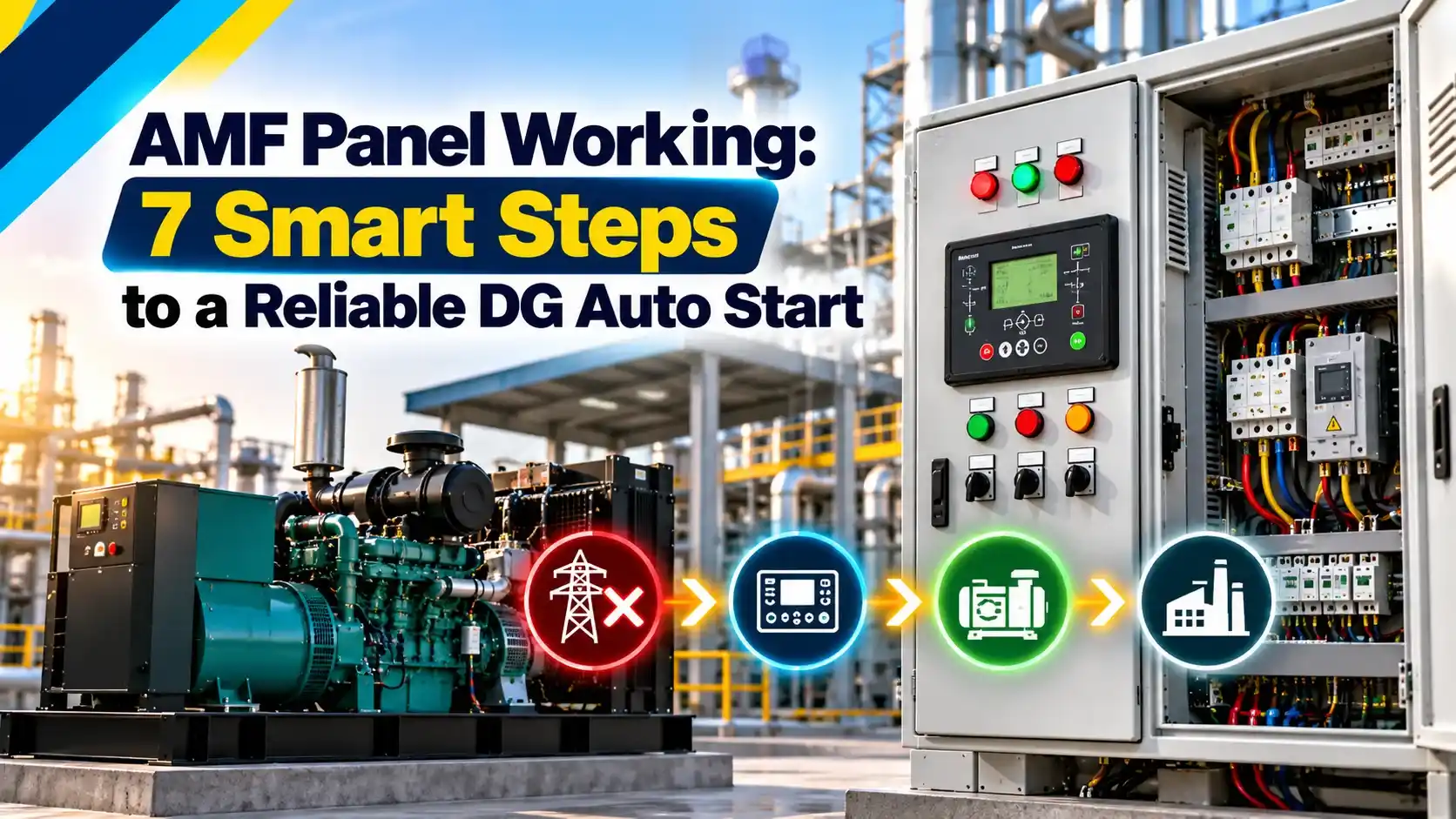
What Is an AMF Panel?
An AMF panel, or automatic mains failure panel, is a control and switching panel that monitors the utility supply, starts a standby diesel generator when the mains fail and transfers the load to it automatically. When the mains return and stay healthy, it transfers the load back and stops the DG after a cooling run.
It combines an engine controller with a changeover arrangement, very similar to an automatic transfer switch. The difference is that the panel also starts, monitors and protects the engine itself.

In India, these panels are standard in hospitals, apartments, telecom sites, banks and factories wherever grid outages are frequent.
Main Parts Inside the Panel
Microprocessor module that senses mains and DG, runs timers, cranks the engine and trips on faults.
Pair of contactors, motorised MCCBs or ACBs that switch the load between mains and DG.
Mechanical, electrical and software locks that stop both sources closing together.
Around the controller, an AMF panel also holds the battery charger, start and fuel relays, meters, current transformers and control fuses. The engine start and stop outputs usually drive heavy duty electromagnetic relays rather than the starter motor directly.
The mains and DG breakers are selected like any feeder breaker, using the full load current and fault level, as shown in how to select the right MCCB rating. For large sets, air circuit breakers are common, and their differences are covered in ACB vs VCB vs SF6 breakers.
Keep the DG battery charger on a supply that the AMF panel does not switch off during a mains failure test. A flat battery is the most common reason a standby set fails to start.
7 Steps of the AMF Panel Operating Sequence
Subtech, an Indian switchgear maker, gives typical values for this sequence. Mains failure detection takes about 0.5 to 2 seconds, DG stabilisation about 10 to 15 seconds, and the mains stabilisation delay before reverse transfer about 5 to 10 minutes.
Subtech also quotes a starter retry interval of about 5 to 10 seconds between crank attempts. As an example of an under voltage setting, it gives 180 V for a 230 V nominal system.
Shenton Group notes that a generator typically needs around 15 seconds after mains failure before the AMF panel transfers the load to it. That short gap is why critical loads still need a UPS.
Mains Sensing and Protection Settings
The AMF panel controller measures all three phase voltages and the frequency of the mains continuously. It declares a failure on under voltage, over voltage, phase loss, phase reversal or frequency outside limits, not only on a total blackout.
| Setting | Typical Value | Purpose |
|---|---|---|
| Under voltage | About 180 V on a 230 V system | Detect a weak or failing supply |
| Over voltage | About 260 V to 270 V | Protect loads from surges |
| Mains fail delay | 0.5 to 5 s | Ignore short dips |
| Crank time | 5 to 10 s per attempt | Protect the starter motor |
| Crank rest | 5 to 10 s | Let battery and starter recover |
| Crank attempts | 3 | Declare fail to start after this |
| Mains return delay | 1 to 10 min | Confirm grid is stable |
| Cooling run | 3 to 5 min | Cool the turbocharger and engine |
These are common starting values, so always follow the engine maker and site needs. Voltage limits must also suit the local grid, since many rural feeders sit low for hours.
Deep Sea Electronics states in its DSE7320 MKII datasheet that the module monitors mains voltage from 15 V to 333 V AC line to neutral and frequency from 3.5 Hz to 75 Hz. It also accepts a DC supply of 8 V to 35 V continuous, which lets it survive the voltage dip during cranking.
How the AMF Panel Starts the DG
To start the engine, the AMF panel first energises the fuel solenoid or ECU, then the crank relay drives the starter motor. It stops cranking as soon as it sees engine speed, from a magnetic pickup, the charging alternator or generator frequency.
If the engine does not fire within the crank time, the AMF panel rests and tries again. After the set number of attempts, it raises a fail to start alarm so that an operator can investigate.
Once running, the controller waits until the generator excitation and AVR bring voltage and frequency inside limits. Only then does it close the DG breaker, which protects motor loads from a weak supply.
Check the crank time setting after any battery or starter change. A crank time that is too long overheats the starter, while one that is too short can stop cranking before a cold engine fires.
Interlocks That Prevent Back Feeding
The most important safety rule of any AMF panel is that the mains and DG breakers must never close together. Paralleling a standalone DG with the grid can damage the engine and can feed the grid lines that linesmen believe are dead.
- Mechanical interlock between mains and DG breakers or contactors.
- Electrical interlock using NC auxiliary contacts in each closing circuit.
- Controller logic that opens one source before closing the other.
- Neutral switching arranged as per the earthing design.
- Phase sequence of DG matched to mains before first use.
- Manual changeover handles lockable and clearly labelled.
In an AMF panel, electrical interlocks alone are not enough, because a welded contact can defeat them. A mechanical interlock bar gives a second, independent layer, just as protective relays are backed up by other devices.
A contactor based changeover typically includes both a mechanical interlock and electrical interlocks through auxiliary contacts. Using both makes it very unlikely that the two supplies ever close together.
Operating Modes and Test Mode
A weekly off load test of the AMF panel proves the starting system, while a monthly on load test proves the alternator, breakers and changeover. Always inform the site before an on load test, because there is a short break in supply.
Maintenance work on the DG should use the Stop mode together with lockout tagout, since an Auto mode panel can crank the engine without warning. That is the most common cause of injuries around standby generators.
Interruption Time Formula
For UPS and process planning, you need to know how long an AMF panel leaves the load dead after a mains failure. The time is the sum of the delays in the start sequence.
n = number of crank attempts needed
Example:
Delay = 2 s, Crank time = 5 s, n = 1, Crank rest = 10 s, Warm up = 10 s, Transfer = 1 s
t = 2 + 5 + 0 + 10 + 1
t = 18 s, about 0.30 min
AMF Panel Interruption Time Calculator
Second Worked Example: A Cold Morning Start
Suppose a cold engine needs all three crank attempts, with the same 2 second delay, 5 second cranks, 10 second rests, 10 second warm up and 1 second transfer. The time becomes 2 + 15 + 20 + 10 + 1 = 48 seconds.
Any UPS feeding servers or a PLC must therefore bridge at least 48 seconds plus margin. You can check this using battery backup time calculation and the UPS types in UPS working principle.
Selection and Commissioning Guide
Start with the DG rating, which comes from the connected and starting loads, as explained in how to calculate generator size. The panel busbars, breakers and cables must carry the DG full load current with margin.
Choose the AMF panel changeover type by rating, with contactors common at lower ratings and motorised MCCBs or ACBs at higher ones. Transfer switching equipment should comply with IEC 60947 part 6 1, and breakers with IEC 60947 part 2.
For large motors, check the voltage dip when they start on the DG, using motor starting voltage dip calculation. Staggered restart of big motors after transfer avoids tripping the DG on overload.
- Starts the DG and restores power without an operator.
- Protects the engine with automatic shutdowns.
- Records events for maintenance and audits.
- Allows scheduled test runs with little effort.
- There is always a break in supply during transfer.
- Wrong settings cause nuisance starts or failed starts.
- Depends on a healthy battery and fuel system.
- Needs regular testing to stay reliable.
Troubleshooting Common AMF Faults
If the DG does not start, check the battery voltage during cranking, the fuel solenoid, the emergency stop circuit and the controller mode. A reading that collapses below about 9 V on a 12 V battery while cranking usually points to a weak battery or loose terminals.
If the DG starts but will not take load, look for a voltage or frequency alarm, a tripped DG breaker or a failed interlock contact. Battery faults are covered in detail in causes of battery failure.
Frequent nuisance starts from an AMF panel usually mean the mains fail delay is too short or the under voltage limit is set too tight for the local grid. Read the controller event log, which the DSE7320 MKII datasheet says can store 250 events.
DSE7320 MKII AMF Controller Datasheet
Panel Wiring and Working Video
AMF Panel FAQ
It is an automatic mains failure panel that watches the grid supply and starts a standby diesel generator when the mains fail. It then transfers the load to the generator without any operator action.
When the mains return and stay healthy, it transfers the load back to the grid. The DG then runs for a short cooling period and stops automatically.
The load is usually dead for about 10 to 60 seconds, depending on delays, cranking and warm up. Subtech quotes DG stabilisation times of about 10 to 15 seconds after starting.
With the example settings in this article, the break is 18 seconds on the first crank. It can reach 48 seconds if the engine needs three attempts.
An ATS only switches the load between two sources that are already available and running. An AMF panel also senses the mains, starts the generator engine, monitors it and stops it after a cooling run.
Many modern panels combine both functions in one enclosure. The AMF controller then drives the motorised transfer switch or contactors as one step of its sequence.
After an outage, the grid often comes back unstable and may fail again within seconds or minutes. The return delay confirms that voltage and frequency stay healthy before the load is moved back.
Subtech quotes typical mains stabilisation delays of about 5 to 10 minutes. This avoids repeated transfers that stress breakers, motors and the generator.
A mechanical interlock between the two breakers or contactors is the first and strongest layer of protection. Electrical interlocks through NC auxiliary contacts and controller logic add further independent layers.
Together they ensure that the generator can never close onto the grid. This protects the engine, the loads and linesmen working on the utility network.
Run a short off load test every week to prove that the engine starts reliably. Run an on load test every month to prove the alternator, breakers and changeover under real load.
Log battery voltage, start time and any alarms during each test. Inform users before an on load test because the load sees a short break.
The most common causes are a weak battery, a faulty fuel solenoid, an active emergency stop or the panel left in Manual or Stop mode. Wrong crank time settings can also stop a cold engine from firing.
Read the event log first to see which alarm was raised. Then measure battery voltage while cranking and check the start and fuel relay outputs.
Related Articles
- Automatic Transfer Switch ATS Explained
- How to Calculate Generator Size for Industrial Load
- UPS Working Principle
- Generator Synchronizing Procedure
- Calculate Battery Backup Time
External References
- DSE7310 MKII and DSE7320 MKII Datasheet, Deep Sea Electronics
- AMF Panel Working, Components and Selection Guide, Subtech
- Transfer Switch, Wikipedia
What We Learn Today
- An AMF panel senses mains failure, starts the standby DG, transfers the load and returns it to the grid automatically once the supply is stable.
- Timers such as mains fail delay, crank time, crank rest, warm up, mains return delay and cooling run decide how the sequence behaves.
- Mechanical and electrical interlocks must ensure that the DG and mains breakers never close together, which prevents dangerous back feeding.